4 Electrical installation
Festo – P.BE-CPX-CMAX-SYS-EN – en 2017-09b – English 43
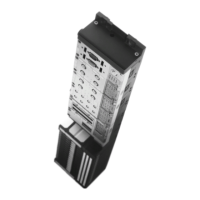
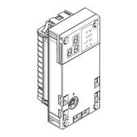
4.3.2 Sensor interface CASM
The sensor interface CASM has an incoming axis connection S1 for connection of the VPWP
(è Section 4.3). The connection S2 serves to connect the displacement encoder (è Tab. 4.6).
Drive Displacement encoder Sensor interface Connecting cable to the
displacement encoder
DGCI Permanently attached Not necessary Permanently connected to the
DDLI Integrated
drive
DNCI
CASM-S-D3-R7
DDPC CASM-S-D3-R7
DNC External, MLO-POT-...-TLF CASM-S-D2-R3 NEBC-A1W3-K-0.3-N-M12G5
External, MLO-POT-...-LWG
NEBC-P1W4-K-0,3-N-M12G5
DSMI Integrated
Tab. 4.6 Overview of sensor interfaces and measuring system cables
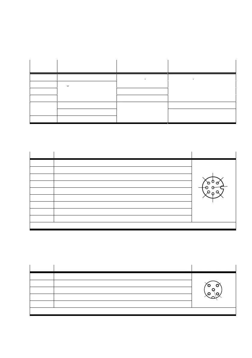
CASM-S-D3-R7
For digital, incremental measuring systems; M12 measuring system connection (socket, 8 pin)
Pin Assignment S2
1 + Ub sensor (5 V)
4
3
7
1
6
5
8
2
2 0 V
3 Signal sine +
4 Signal sine –
5 Signal cosine –
6 Signal cosine +
7 Screening
8 n.c. (not connected)
Housing Earth terminal (FE)
The cable screening is connected to the earth terminal of the sensor interface.
Tab. 4.7 Pin assignment of connection S2 at the CASM-S-D3-R7
CASM-S-D2-R3
For analogue, absolute measuring systems (potentiometer); M12 measuring system connection (sock
et, 5 pin)
Pin Assignment S2
1 Displacement encoder housing
3
2
4
1
5
2 n.c. (not connected)
3 Analogue GND (AGND)
4 Analogue input 0 ... 5 V (INPUT)
5 Earth terminal (FE)
The cable screening is connected to the earth terminal of the sensor interface.
Tab. 4.8 Pin assignment of connection S2 at the CASM-S-D2-R3