4 Electrical installation
Festo – P.BE-CPX-CMAX-SYS-EN – en 2017-09b – English 47
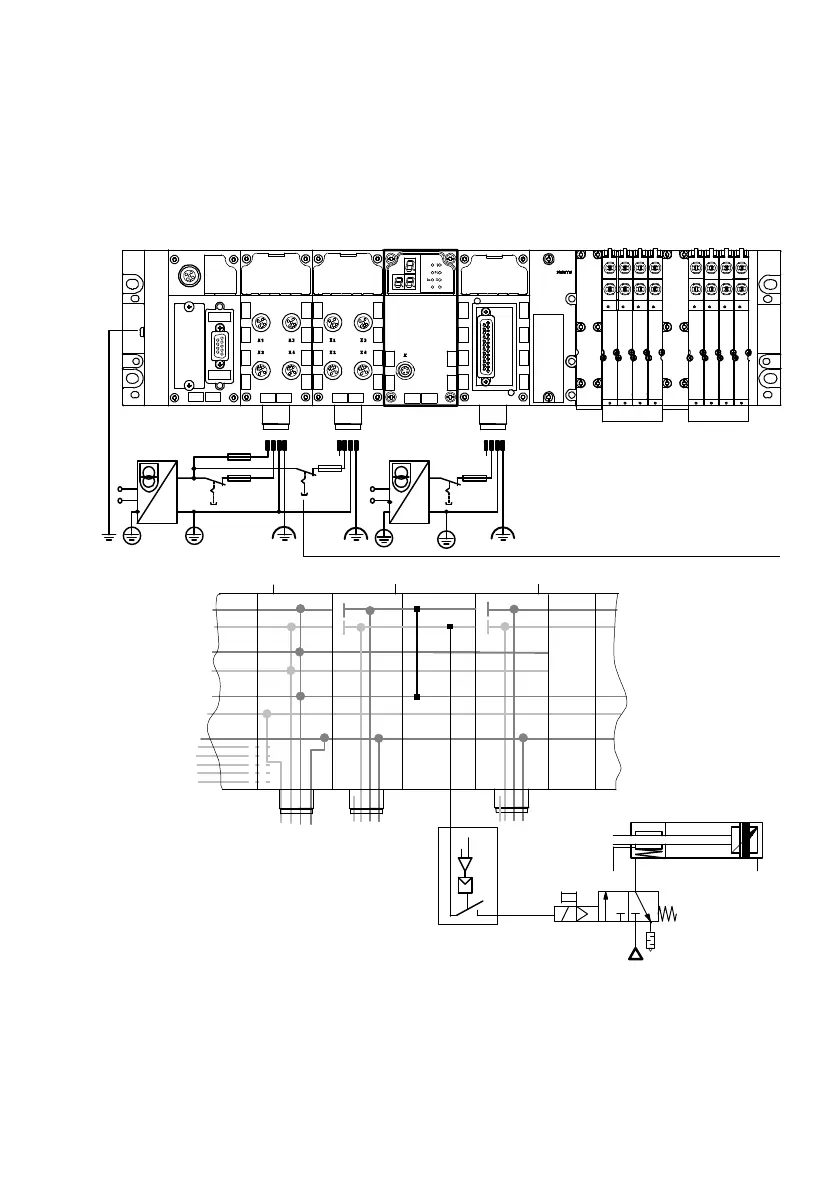
Shut-down of the load voltage in connection with a brake or clamping unit
In the following example, circuitry for a brake or clamping unit is connected to the digital output of the
VPWP. During switch-off (è Fig. 4.2, 1 ) or failure of the load voltage for the valves (U
VAL
) of the
CMAX, the brake or clamping unit is activated. The brake or clamping unit can also be controlled by the
higher-level PLC using a program via the digital output of the VPWP (è Fig. 4.2, 3 ).
8DI
8DI4DO
MPA
1 2 34 1 2 341 2 34
0 V (U
VAL
)
24 V DC (U
VAL)
0 V (U
OUT)
24 V DC (U
OUT)
0 V (U
EL/SEN)
24 V DC (U
EL/SEN)
FE
1
2
3
CPX-(M)-GE-EV-S CPX-(M)-GE-EV-V CPX-(M)-GE-EV-V
1 Switching off the load voltage possible
2 Output VPWP
3 Activation/Deactivation of the brake/clamping
unit by the higher-level PLC
Fig. 4.2 Switching off of the load voltage supply of the output at the VPWP together with the valve
load supply (example)