1. Installation
1−26
Festo P.BE−CPX−FB13−E N en 0811c
System supply,
additional supply and
valve supply
The CPX terminal is supplied with operating and load power
via the manifold base with system, add
itional and valve
supply. Further manifold bases are in preparation.
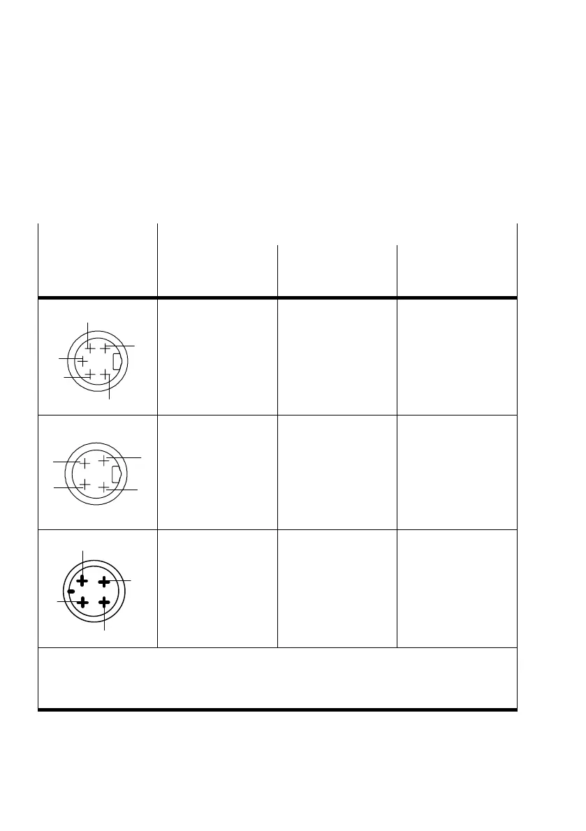
Plugs
Pin assignment of manifold base with
system power supply
type CPX−GE−EV−S...
type CPX−M−GE−EV−S...
additional power supply
type CPX−GE−EV−Z...
type CPX−M−GE−EV−Z...
valve power supply
type CPX−GE−EV−V...
7/8"−5PIN
1
2
3
4
5
1: 0 V
VAL
/ 0 V
OUT
2: 0 V
EL/SEN
3: Earth terminal
(incoming)
4:24 V
EL/SEN
5: 24 V
VAL
/ 24 V
OUT
1: 0 V
OUT
2: free (not connected)
3: Earth terminal
(incoming)
4:free (not connected)
5: 24 V
OUT
D
C
B
A
7/8"−4PIN
1)
A:24 V
EL/SEN
B:24 V
VAL
/ 24 V
OUT
C: Earth connection
D:0 V
EL/SEN
/
0 V
VAL
/ 0 V
OUT
(incoming)
A: not connected
B:24 V
OUT
C: Earth connection
D:0 V
OUT
(incoming)
A:free (not connected)
B:24 V
VAL
C: Earth connection
D:0 V
VAL
(incoming)
2
3
4
1
M18
1: 24 V
EL/SEN
2: 24 V
VAL
/ 24 V
OUT
3: 0 V
EL/SEN
/
0 V
VAL
/ 0 V
OUT
4: Earth terminal
1: free (not connected)
2: 24 V
OUT
3: 0 V
OUT
4: Earth terminal
1: free (not connected)
2: 24 V
VAL
3: 0 V
VAL
4: Earth terminal
1)
Note the specifications on the plug
V
EL/SEN
:Operating voltage for electronics/sensors
V
OUT
: Load voltage for outputs
V
VAL
: Load voltage for valves
Tab.1/10: Pin assignment for system supply, additional supply and valve supply