A. Technical appendix
A−18
Festo P.BE−CPX−FB13−EN en 0811c
A.3.3 Examples for DPV1 access
Example of access to data records
In the following, the module parameter Reaction after short
circuit/overload of the load voltage supply" is modified on
module no. 3 from Fig.2/3 in the configuration example.
Since slot number = module number + 100 (see above),
slot103 should be
used for module no. 3 in the following.
As an initial setting, bit 1 of parameter 1 has the value
1" = Switch voltage on again".
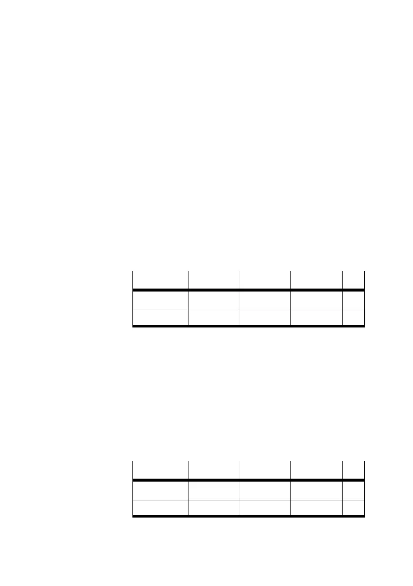
1. Assign the command box as follows:
Byte
1 2 3 4
Contents
Slot no. Index no. Offset
Example
103 21 1
2. Then transfer the value 0" with the Write Box.
The module is now parameterised to Leave voltage
switched off" in the event of a short circuit/overload.
Example of access to the diagnostic memory
In the following, entry 0 of the diagnosis memory will
be read
out indirectly via the command box.
1. Assign the command box as follows:
Byte
1 2 3 4
Contents
Slot no. Index no. Offset
Example
1 21 0
2. Read out the diagnostic memory with the Read Box.