2. Commissioning
2−16
Festo P.BE−CPX−FB13−EN en 0811c
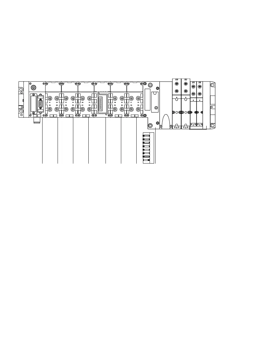
Example 2: CPX terminal with VTSA pneumatics
01 2 3 4
1234 567 8
56
8DI 8DI 4DO 8DI 2AI
Module no.:
8DO
OPEN
12345678
8 O
7
2AO
1 Field bus node CPX−FB13
2 Digital 8−input module
3 Digital 8−input module
4 Digital 4−output module
5 Digital multi I/O module
6 Analogue 2−input module
7 Analogue 2−output module
8 Pneumatic interface for CPA
pneumatics (with DIL switch set to
1Ū8 valve coils)
Fig.2/3: Example terminal 2 (with VTSA pneumatics)
Configure the CPX terminal module−by−module from left to
right. The following table shows the configuration of the
above terminal example: