2. Commissioning
2−8
Festo P.BE−CPX−FB13−EN en 0811c
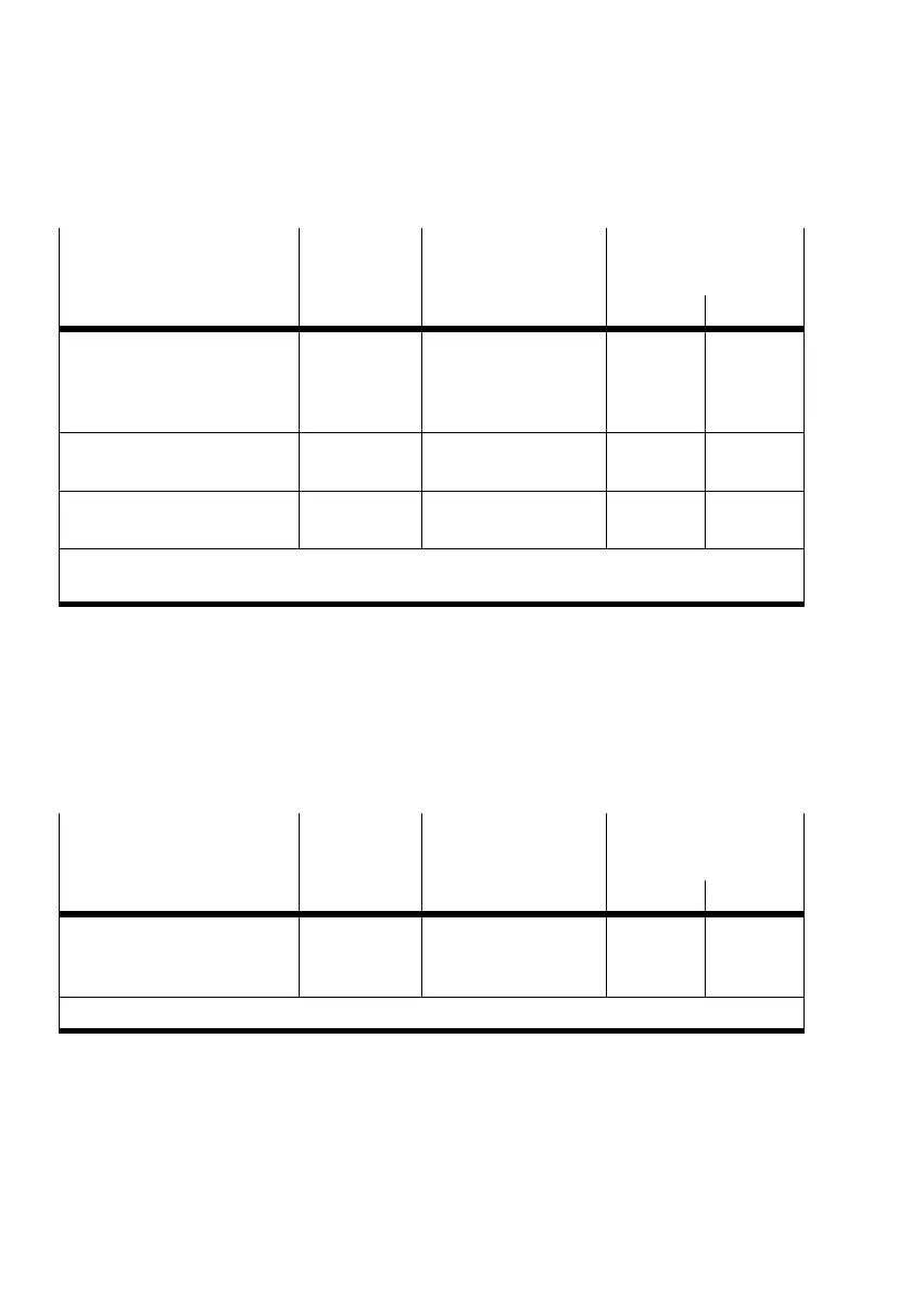
Electric modules
Module
identifier
1)
Identifier
Siemens/EN 50170
Assigned address
space
Description Inputs Outputs
CPX−CP interface:
CPX−CP−4−FB
CPI 192 / C0
h
, 0F
h
, 0F
h
2)
max. 4
bytes per
string/
128 I
max. 4
bytes per
string/
128 O
Soft−stop end−position
controller: CPX−CMPX
CMPX−C−1−H1 53 / 35
h
3 words/
48 I
3 words/
48 O
Multi−axis interface:
CPX−CMXX
CPX−CMXX 192 / C0
h
, 0F
h
, 0F
h
16 byte/
128 I
16 byte/
128 O
1)
Module identifier in the handheld unit or in the hardware configuration of the programming software
2)
Dependent on the last CP string used, example for maximum assignment
Tab.2/4: Module overview and address assignment part 4: Technology modules
Operating mode
RemoteController
In the Remote Controller operating mode, only the identifier
of the field bus node will be configured (see section 2.1.5):
Electric modules
Module
identifier
1)
Identifier
Siemens/EN 50170
Assigned address
space
Description Inputs Outputs
Field bus node
(Remote controller)
(FB13: CPX−8 bytes I/8 bytes O)
FB13−RC 192 / C0
h
, 07
h
, 07
h
8 byte/
64 I
8 byte/
64 O
1)
Module identifier in the handheld unit or in the hardware configuration of the programming software
Tab.2/5: Configuration of the field bus node for the operating mode Remote Controller