3. Installation
3-34
Festo P .BE-MPA-EN en 1108e
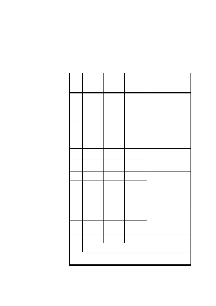
For controlling the valves, each solenoid coil is assigned to a
certain pin of the multi-pin plug socket.
Pin
Address Valve
position
number
Solenoid
coil
Electronics module
1
2
0
1
0 14
12
VMP A 1-MPM-EMM-8
(for 4 MPA1 v alv es each
with two solenoi d coils)
3
4
2
3
1 14
12
5
6
4
5
2 14
12
7
8
6
7
3 14
12
9 8 4 14 VMPA 2-MPM-EMM-2
(for2MPA2valves,
each with one solenoid
coil)
10 9 5 14
11 10 6 14 VMP A1-MPM-EMM-4
(for 4 MPA1 v alves,
each with one solenoid
coil)
12 11 7 14
13 12 8 14
14 13 9 14
15
16
14
15
10 14
12
VMP A 2-MPM-EMM-4
(for2MPA2valves,
each with 2 solenoid
coils)
17
18
16
17
11 14
12
... ... ... ... ...
25 0V
1)
1)
Connect 0 V with positive-switching control signals, 24 V with
negative-switching control signals; mixed operation is not permitted.
Tab. 3/10: Example: Address assignment of the MPA-S
valve terminal with multi-pin plug connection
and 12 valve locations