2. Fitting
2-7
Festo P.BE-MPA-EN en 1108e
3. Mount the H-rail clamping units at all required mounting
points (see Tab. 2/2). Make sure that the clamping
component lies horizontally with respect to the H-rail.
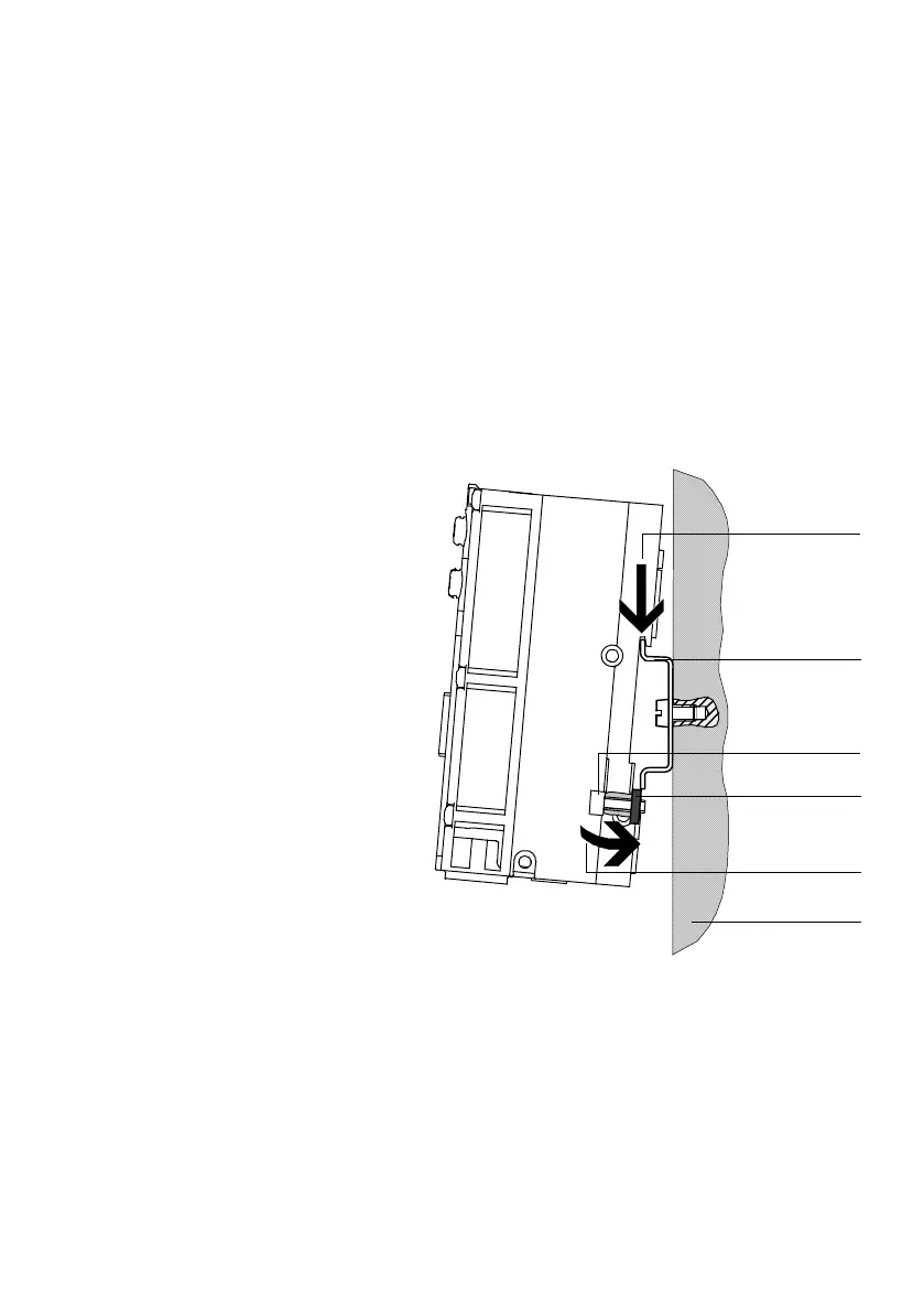
4. Hang the MPA-S valve terminal onto the H-rail
(see Fig. 2/1, arrow A).
5. Swing the MP A-S valve terminal onto the H-rail
(see Fig. 2/1, arrow B).
1 H-rail
2 Retaining screw
of the H-rail
clamping unit
3 Clamping
component of the
H-rail clamping
unit
4 Mounting surface
(A)
(B)
1
2
3
4
Fig. 2/1: Mounting of the MPA-S valve terminal on an H-rail
6. Turn the clamping components for mechanical locking
vertically behind the H-rail (see Fig. 2/2, arrow A);
then tighten the retaining screws of the H-rail clamping
with 1.3 Nm to secure the MPA-S valve terminal against
tilting or sliding.