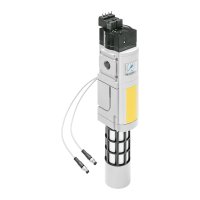
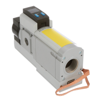
MS6-SV-...-E-10V24
Festo – MS6-SV-...-E-10V24 – 1310b English 59
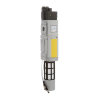
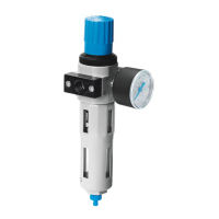
5.2 Pneumatic installation
5.2.1 Pneumatic por ts 1 and 2
If using fittings with spanner size larger than SW24:
• Remove the cover cap MS6-END (push upwards), if available.
If using fittings:
• Observe the permissible screw-in depth of the connecting thread of 10 mm.
For larger screw-in depths, the sub-bases MS6-AG…/AQ from Festo must be used.
• Make sure that the compressed air line is connected correctly.
• Screw the fittings into the pneumatic ports using appropriate sealing material.
5.2.2 Pneumatic por t 3
When exhausting a system through the MS6-SV-E, high sound pressure levels are generated. We th ere-
fore recommend that you use a silencer.
Note
Warning
Loss of the safety function
If a commercially-av ailable silencer is used, the body of the silencer may become
clogged, which c an result in reduced exhaust performance (back pressure), which can
lead to a c omplete loss of the safety function.
• Use the safety silencer designed for the device UOS-… ( chapter 12 “Accessor-
ies”).
• Only use a commercially available silencer if it will be employed in combination with
a back pressure monitor ing system. In a dditio n, the silencer must be checked regu-
larly by ser vice staff and replaced, if necessary.
• Screw the silencer into the pneumatic port 3.
• Make sure that there is unrestricted air venting. Neither the silencer nor por t 3 may be blocked.