MS6-SV-...-E-10V24
Festo – MS6-SV-...-E-10V24 – 1310b English 63
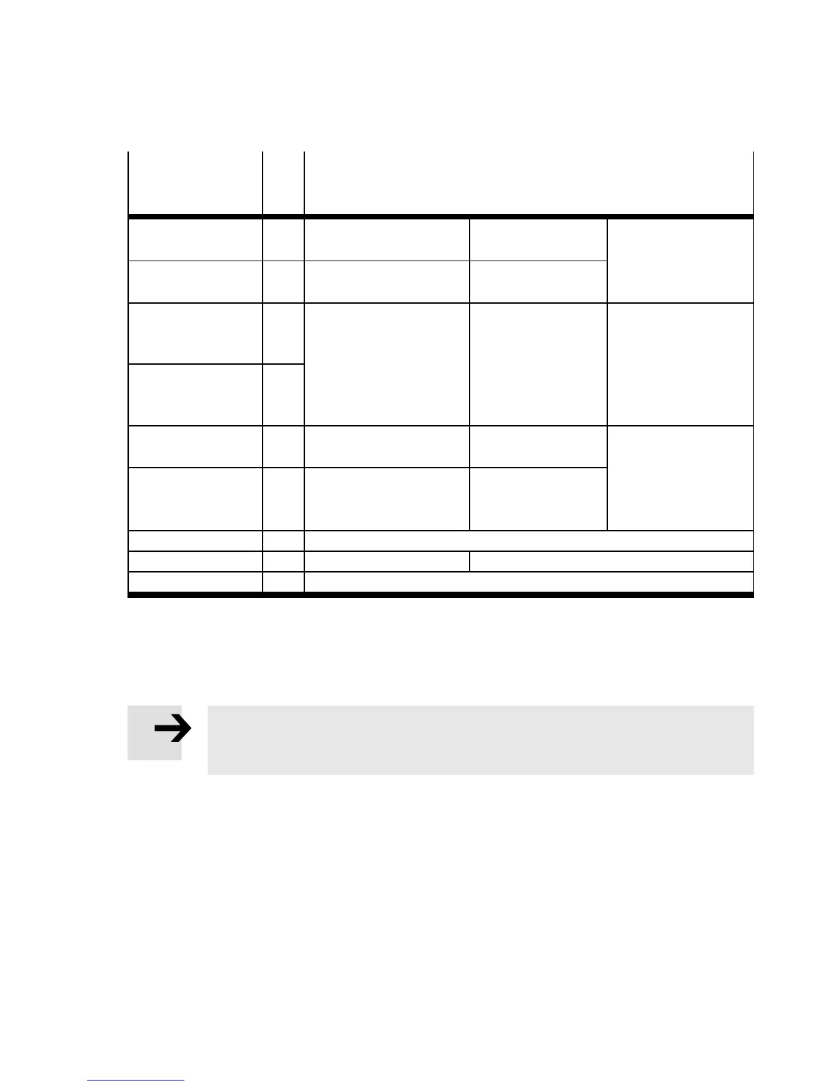
6.3 Inputs and outputs
Terminal in
multi-pin plug
socket NECA-...
I/O Allocation
1 EN1 Enable signal 1 (static or
dynamic)
Input 0 V/24 V
(E N 61131-2 type 2)
Section 4.3
“Connection
examples”
2 EN2 Enable signal 2 (static or
dynamic)
Input 0 V/24 V
(E N 61131-2 type 2)
3 13 Signal contact, NO Potential-free
contact
(sem iconductor
relay),
Max. 120 mA
Max. 60 V DC
Section 4.4
“Signal contact”
4 14
5 A5 Contact for “Automatic
start” operating mode
–
Section 4.1 and
4.3
6 S34 Contact for “Automatic
start” or “Monitored
start” operating mode
Input 0 V/24 V
(E N 61131-2 type 2)
7 – –
8 +L1 Operating voltage +24 V DC ±10 %
9 M GND
Tab. 4 Terminal assignment
7 Commissioning
Note
For easier commissioning, we recommend planning a reset button (normally closed) in
the power supply circuit. This simplifies resetting in case of error.
The following description o f commissioning is graphically supporte d by the diagrams on the next pages
(with multi-pin plug socket NECA-S1G9-P9-MP1 Fig. 20; with multi-pin plug socket NECA-
S1G9-P9-MP3/MP5 Fig. 22). The diagrams show the switching characteristics of the inputs and
outputs in normal operation (if the “Automatic start” operating mode has been set). The operator’s
actions are marked in the diagram by an arrow.
To commission the device, proceed as follows:
1. Apply operating pressure p1.
2. Switch on the operating voltage. The MS6-SV-E automatically tests itself for errors.
• Power LED ( green)
– illuminates during self test for around 6 s
– flash es green after successful self test,