MS-9200UDLS/E/C Manual — P/N 52750:F 7/26/2010 25
Accessories Product Description
Wiring Configuration
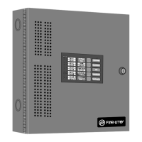
Figure 1.3 illustrates the wiring between the FACP’s Primary ANN-BUS and ANN-BUS devices.
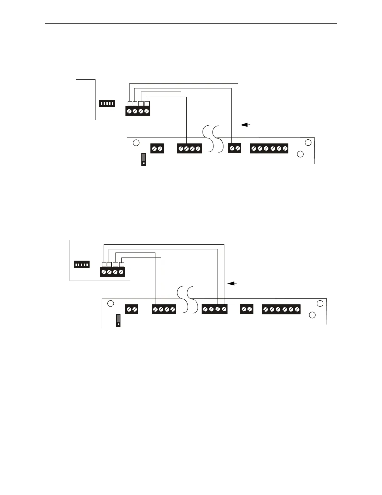
Figure 1.4 illustrates the wiring between the FACP’s Secondary ANN-BUS and ANN-BUS
devices.
Powering Both ANN-BUS Circuits Simultaneously
When simultaneously using the Primary and Secondary ANN-BUS circuits on the FACP, power
can be shared from the Nonresettable Power output on TB1. Alternately, one ANN-BUS can be
powered by the Resettable Power output (TB1 Terminals 3 and 4) once it is reconfigured as Nonret-
table Power using JP6. This provides the benefit of independently acting power-limiting for the
two ANN-BUS circuits (required for Canadian applications).
B+ A+ B- A- A B
ANN
ACS
SHIELDSLC
SLC
SLC
SLC
TB9
TB10
TB1
B A (+) (-)
4 3 2 1
A B
+ -
+ 24V -
NON-RST
POWER
+ 24V -
RST
POWER
TB1
JP7
1
2
3
+ -
REMOTE PWR
SUPPLY SYNC
+ -
TB2
Figure 1.3 Primary ANN-BUS wiring to ANN-BUS Device
ANN-BUS Device
MS-9200UDLS
ANN-BUS and power wiring are
supervised and power-limited
24 VDC
nonresettable
Primary ANN-BUS
92udlsctoann80.wmf
+ 24V -
NON-RST
POWER
+ 24V -
RST
POWER
B+ A+ B- A- A B
ANN
ACS
SHIELD
SLC
SLC
SLC
SLC
TB1
TB8
TB9
TB10
JP7
1
2
3
TB1
B A (+) (-)
4 3 2 1
A B
+ -
+ -
REMOTE PWR
SUPPLY SYNC
+ -
TB2
Xmt Rcv Dtr Gnd
Figure 1.4 Secondary ANN-BUS wiring to ANN-BUS Device
ANN-BUS Device
MS-9200UDLS
ANN-BUS and power wiring are
supervised and power-limited
24 VDC
nonresettable
Secondary ANN-BUS
92udlsc2toann80.wmf