MS-9200UDLS/E/C Manual — P/N 52750:F 7/26/2010 39
Accessories Product Description
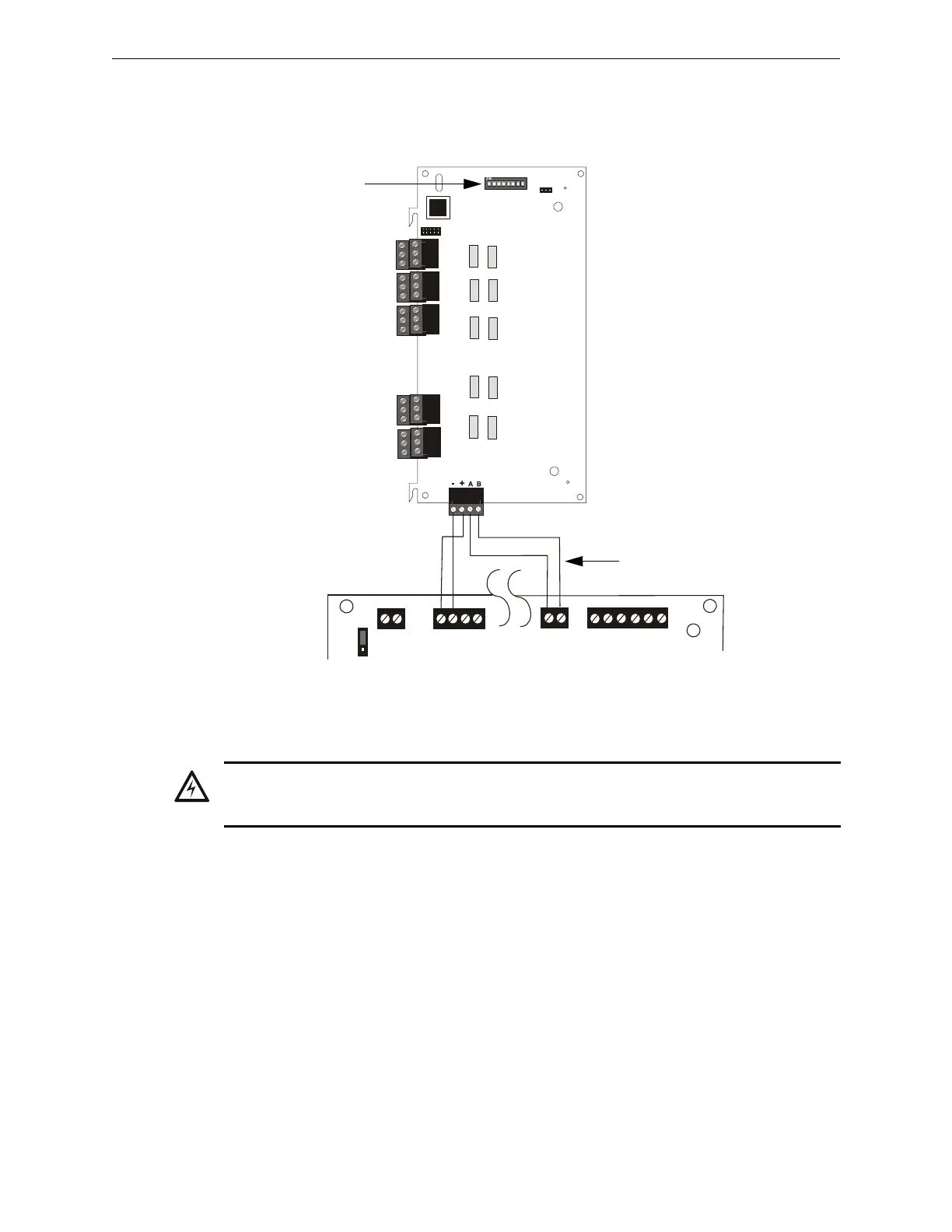
ANN-RLY Board Layout and Connection to FACP
Figure 1.15 illustrates the ANN-RLY board showing locations of screw terminals for connection to
the FACP and the DIP switches for selecting the ANN-BUS ID number.
ANN-BUS Audio Panel Control
The FACP is capable of providing automated activation of the ACC-25/50(ZS/T) zoned system
speaker circuits. To do this, the FACP must be enabled to communicate with the ACC-25/50ZS
Audio Panel over the ANN-BUS (refer to “ANN-BUS Enabled” on page 120). This is accom-
plished by programming the Audio Panel ANN-BUS address into the FACP (refer to “Modules
Installed” on page 120). For details on setting the ANN-BUS address and programming the audio
panel, refer to the ACC-25/50ZS Series Audio Panel manual (document #51889).
The ACC-25/50ZS Series audio panel connects to the FACP via the ACS/ANN-BUS communica-
tion circuit. Zones 33 - 56 on the FACP correspond to the ACC-25/50ZS Series audio circuits 1 -
24. Zone 32 on the FACP serves as the All-Call zone and will activate all audio panel output cir-
cuits. The programmer can select which of the five audio messages at the audio panel will play
when an FACP input zone goes into alarm (refer to“Zone Message” on page 97). The message will
play over the corresponding audio panel output circuit.
Examples:
TB1
J1
SW1
JP2
ANN-BUS
1 2 3 4 5 6 7 8
TB6
TB3
TB5
TB4
TB2
ANN
ACS
SHIELDSLC
SLC
SLC
SLC
TB9
TB10
+ -
+ 24V -
NON-RST
POWER
+ 24V -
RST
POWER
TB1
JP7
1
2
3
+ -
REMOTE PWR
SUPPLY SYNC
+ -
TB2
Figure 1.15 ANN-RLY Board Layout and Connection to FACP
ANN-RLY
Primary ANN-BUS
+24 VDC -24 VDC
ANN-BUS and power wiring are
supervised and power-limited
92udlsctorly.wmf
MS-9200UDLS
ANN-BUS (ID#)
Address DIP switch
WARNING: RISK OF ELECTRICAL SHOCK AND EQUIPMENT DAMAGE
DISCONNECT ALL SOURCES OF POWER (AC AND DC) BEFORE INSTALLING OR REMOVING
ANY WIRING.