30 MS-9200UDLS/E/C Manual — P/N 52750:F 7/26/2010
Product Description Accessories
The following table shows the ANN-80 connections to the MS-9200UDLS.
Programming
Following installation and wiring of the ANN-80 LCD annunciator to the FACP, the annunciator
must be added to the system via FACP programming. Refer to the programming section titled
“ANN-BUS Options” on page 120 in this manual for detailed programming information. Select
the LCD option for programming.
Trouble Response
If the ANN-80 is installed but the ANN-BUS is not enabled at the FACP, the ANN-80 will indicate
a trouble condition by NOT turning on its AC Power indicator. The LCD will also display Key Bus
Trouble and the piezo will sound approximately once every 10 seconds. Note that the FACP will
provide no indication of an ANN-80 trouble.
To clear the ANN-80 trouble condition, enable the ANN-BUS and program the address correspond-
ing to the address set on the ANN-80 at the FACP.
ANN-S/PG Serial/Parallel Interface Installation
The ANN-S/PG Serial/Parallel Interface module allows the connection of a remote serial or parallel
printer to the FACP for a real-time log of system events, detector status reports and event history.
The module is provided with a plastic enclosure for surface mounting. Proceed with the installation
as described in the following:
1. Ensure that all power (AC and DC) has been removed from the FACP.
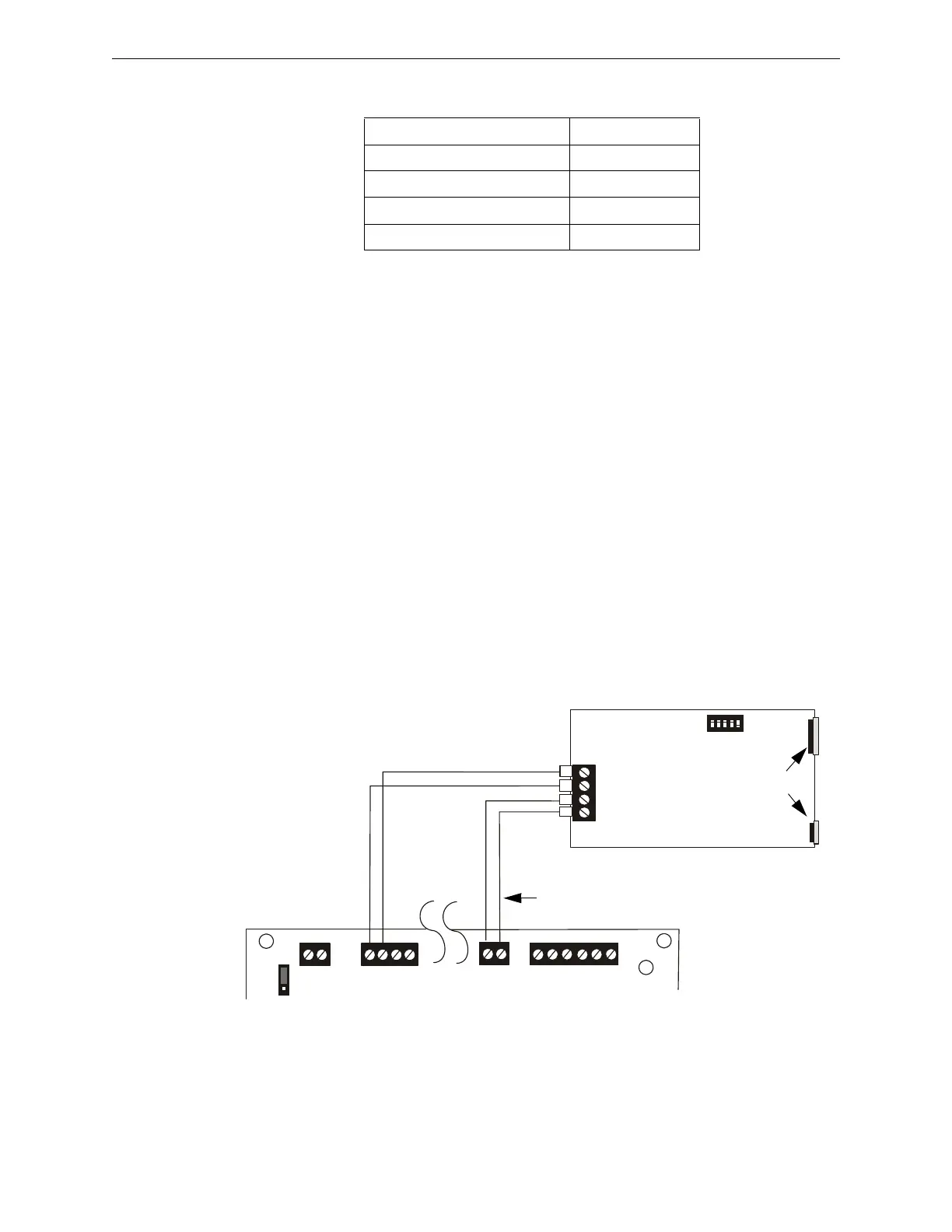
2. Connect the ANN-S/PG to the FACP as illustrated in Figure 1.7
3. Using the DIP switches on the back of the ANN-S/PG module, assign an ID number (address)
to the module
MS-9200UDLS ANN-80 (TB1)
Terminal GND (-) on TB1 Terminal 1 (-)
Terminal PWR (+)TB1 Terminal 2 (+)
Terminal Data (A) on TB9 Terminal 3 (A)
Terminal Data (B) on TB9 Terminal 4 (B)
(-)
(+)
A
B
B+ A+ B- A- A B
ANN
ACS
SHIELD
SLC
SLC
SLC
SLC
TB9
TB10
A B
+ -
+ 24V -
NON-RST
POWER
+ 24V -
RST
POWER
TB1
JP7
1
2
3
+ -
REMOTE PWR
SUPPLY SYNC
+ -
TB2
Figure 1.7 ANN-S/PG Connection to FACP
ANN-S/PG Module
MS-9200UDLS
Cable Connectors for
connection to printer
Parallel
Serial
ANN-BUS and power wiring are
supervised and power-limited
24 VDC
nonresettable
Primary ANN-BUS
92udlsctospg.wmf