MS-9200UDLS/E/C Manual — P/N 52750:F 7/26/2010 49
Power Installation
2.3 Power
2.3.1 AC Power and Earth Ground Connection
Primary power required for the FACP is 120 VAC, 60 Hz, 2.0 amps
for the MS-9200UDLS or 220/240 VAC, 50 Hz, 1.2 amps for the
MS-9200UDLSE. Overcurrent protection for this circuit must com-
ply with Article 760 of the National Electrical Code (NEC) and/or
local codes. Use 14 AWG (2.00 mm
2
) or larger wire with 600 volt
insulation rating. Make certain that the AC mains circuit breaker is
off
before wiring any connections between the mains and the control
panel. Connect wiring from the AC mains to TB11 on the FACP,
being careful to observe proper connections.
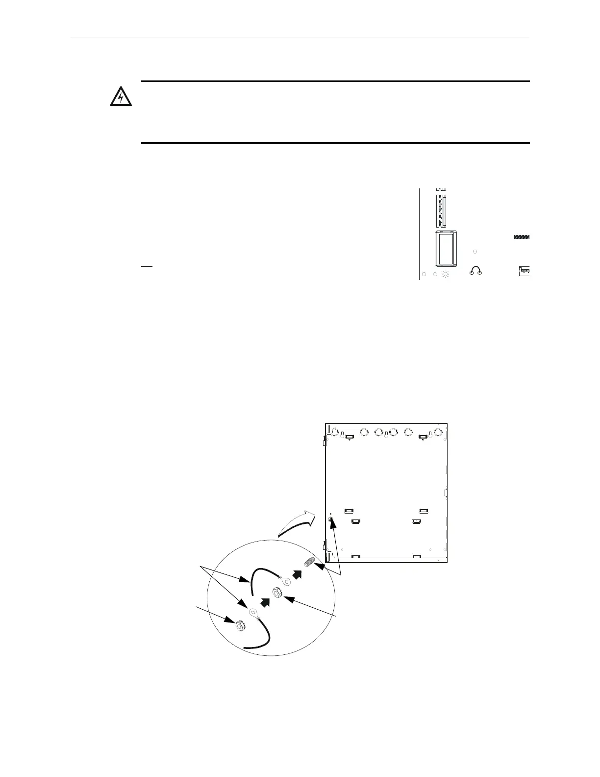
Remove the two keps nuts from the grounding stud in the backbox. Connect the incoming earth
ground wire to supplied cable #71073 with a wire nut. Position the ring terminal end over the
grounding stud. Secure with one of the keps nuts. Place the ring terminal from the other supplied
ground cable #71073 over the ground stud and secure with the second keps nut. Wire the ground
cable to the bottom position of TB11. Refer to Figure 2.1 on page 45 for location of the stud. This
connection is vital in reducing the panel’s susceptibility to transients generated by lightning and
electrostatic discharge. Apply AC power to the panel only after the system is completely installed
and visually checked. Note that AC power must be applied to the panel before installing the battery
interconnect cable (refer to the following section).
WARNING: RISK OF EQUIPMENT DAMAGE AND PERSONAL INJURY
SEVERAL DIFFERENT SOURCES OF POWER CAN BE CONNECTED TO THIS PANEL.
DISCONNECT ALL SOURCES OF POWER BEFORE SERVICING. THE PANEL AND
ASSOCIATED EQUIPMENT MAY BE DAMAGED BY REMOVING AND/OR INSERTING CARDS,
MODULES OR INTERCONNECTING CABLES WHILE THIS UNIT IS ENERGIZED.
J10
H
O
T
N
E
U
T
E
A
R
T
H
TB11
J11
TRANSFORMER 1
2
JP5
Figure 2.5 Earth Ground Connection
9
2
0
0
g
r
n
d
.
w
m
f
grounding stud
keps nut
keps nut
Grounding
Cable #71073