Assembly
5.1 Preparatory work
M4602-02en Edition 09/2022 31
FLUDEX
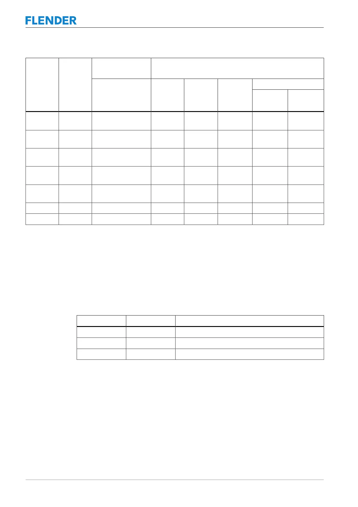
Size
N-EUPEX
Size
Maximum bore D1
1)
mm
Maximum bore D2
1)
mm
Part 120 Part 1
FNA
Part 11
FND
Part 11, 32
FNDS
SB (32) /
HB (11)
Part 32 (brake drum)
FNDB
D x B
D
2
370 180 80 80 70 80 315 x 118
400 x 150
80
90
425 200 100 85 80 80 315 x 118
400 x 150
80
90
490 225 110 90 90 90 400 x 150
500 x 190
90
110
565 250 120 100 100 100 400 x 150
500 x 190
100
110
655 315 135 120 110 100 500 x 190
630 x 236
110
140
755 350 150 140 120 140 630 x 236 140
887 440 170 160 130 140 710 x 265 160
Table5-2: Maximum bores for the hub parts
1)
Maximum bore for parallel keyway in accordance with DIN6885/1.
5.1.2 Mill the parallel keyway5.1 Preparatory work
Position of the parallel keyway
The table below states the required position for the parallel keyway in the coupling parts.
Coupling part Coupling Position of the parallel keyway
1 N‑EUPEX Centred between the flexible element bridges
11 / 32 FLUDEX Beneath a threaded hole
120 FLUDEX 90° to the threaded hole
Table5-3: Position of the parallel keyway
Applicable standards
• Machine the parallel keyway according to DIN6885/1ISOJS9 .
• If you want to mill a parallel keyway that does not correspond to DIN6885/1, please con-
sult Flender.
5.1.3 Machining an axial locking mechanism5.1 Preparatory work
The coupling part is secured by a set screw or an end plate to prevent axial movements.