Assembly
5.3 Aligning the coupling
M4602-02en Edition 09/2022 39
5.3.2 Possible misalignment5.3 Aligning the coupling
The following types of misalignment can occur:
6
PLQ
6
PD[
¨.D
¨.Z
¨.U
6
PLQ
6
PD[
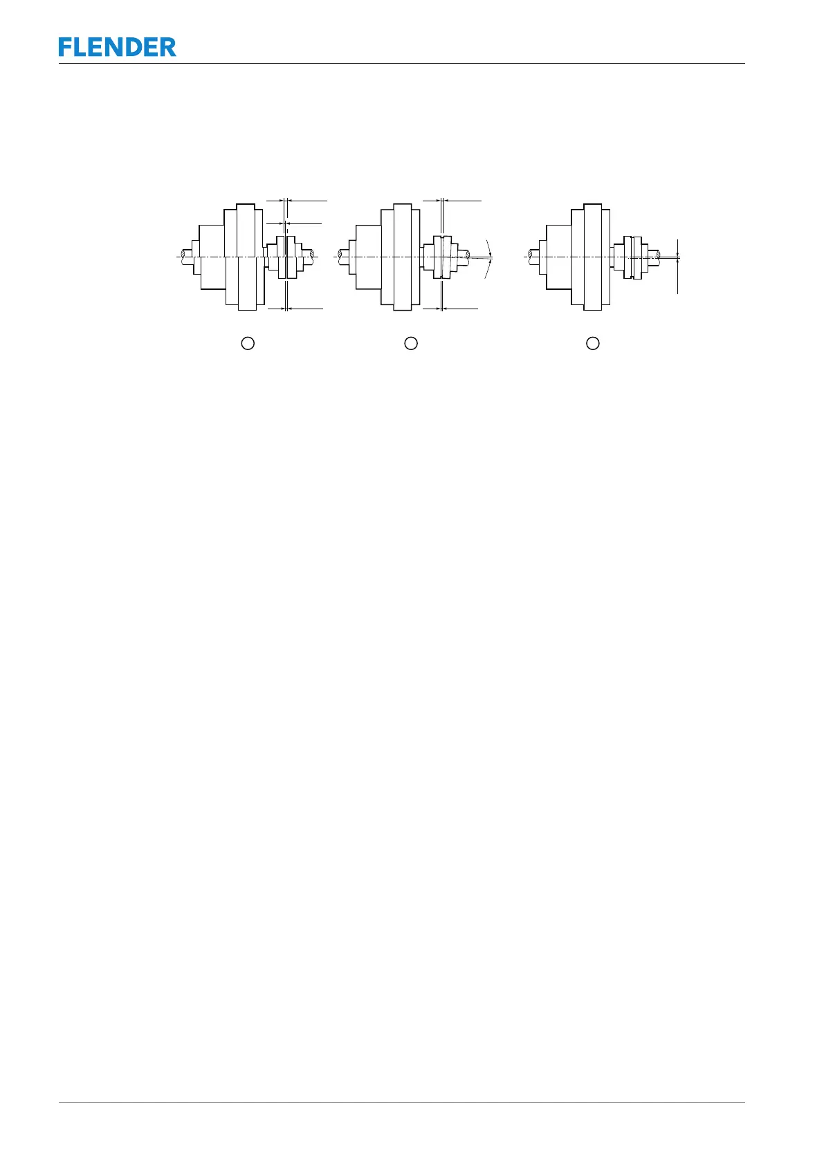
Figure5-6:Possible misalignments
① Axial misalignment (ΔKa)
② Angular misalignment (ΔKw)
③ Radial misalignment (ΔKr)
5.3.2.1 Axial misalignment5.3 Aligning the coupling
Set the axial misalignment ΔKa to a value within the permissible tolerance range for the “S”
clearance.
The values for clearance “S” can be found on the cover sheet or in the order-related coupling
drawing.
5.3.2.2 Angular misalignment5.3 Aligning the coupling
Determine the value ΔS (ΔS = S
max
- S
min
). The determined value ΔS may not exceed the
value ΔS
perm
. The values for ΔS
perm
can be found in Chapter Shaft misalignment values dur-
ing operation (Page79).
If required, you can calculate the angular misalignment ΔKw as follows:
ΔKw[rad]=ΔS/ D3
ΔKw[degrees]=(ΔS/D3)·(180/π)
If required, you can calculate the permissible angular misalignmentΔKw
perm
as follows:
ΔKw
perm
[rad]=ΔS
perm
/ D3
ΔKw
perm
[degrees]=(ΔS
perm
/D3)·(180/π)
D3 corresponds to N-EUPEX size in mm
For N-EUPEX size, see Chapter Shaft misalignment values during operation (Page79).
ΔS
perm
see Section Shaft misalignment values during operation (Page79).
5.3.2.3 Radial misalignment5.3 Aligning the coupling
Determine the value ΔKr. The determined value ΔKr may not exceed the value ΔKr
perm
.
You can find the permissible radial misalignment ΔKr
perm
in Section Shaft misalignment val-
ues during operation (Page79).