Assembly
5.2 Mounting the coupling
M4602-02en Edition 09/2022 35
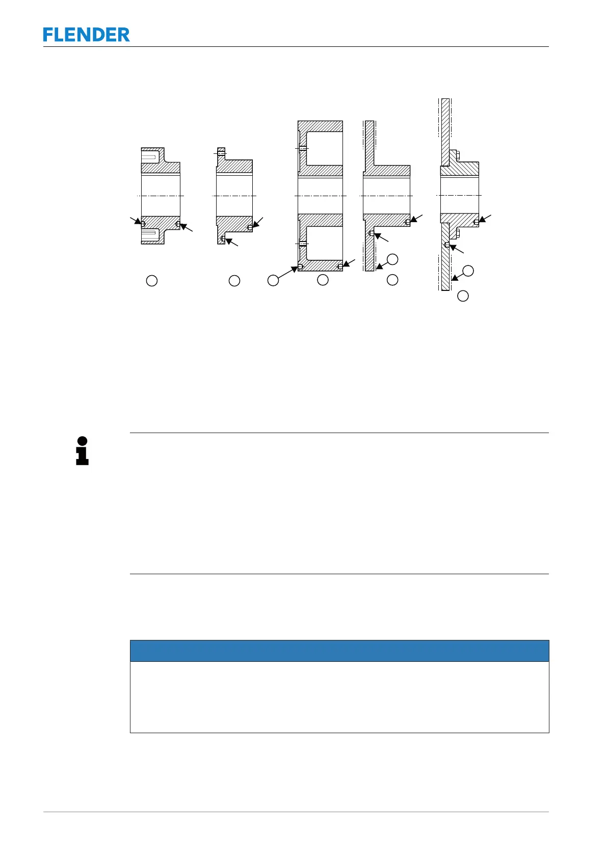
Figure5-4:Position of the balancing bore for two-plane balancing
① Coupling part 1
② Coupling part 11
③ Balancing bore
④ Coupling part 32
⑤ Coupling part 32
⑥ Braking surface
⑦ Coupling part 11 screwed to brake disk (8)
Information
A better balancing result can be achieved by balancing the coupling parts when they are
bolted together as an assembly unit.
Balance the following coupling parts as assembly units:
• Brake drum (32) or brake disk (32), as well as coupling part 11 (11) together with coup-
ling part 10 (10)
• Coupling part 11 (11) of the FNDB‐HB together with coupling part 10 (10) and brake
disk (8)
• When total balancing, mark the position of the components relative to one another.
5.2 Mounting the coupling5.2 Mounting the coupling
NOTICE
Coupling damage, damage to further components
Risk of damage to the coupling through fitting forces by way of the aluminium housing.
• Ensure that the fitting forces are not applied via the aluminium housing.
• Use suitable hoisting gear.