Assembly
5.1 Preparatory work
M4602-02en Edition 09/2022 33
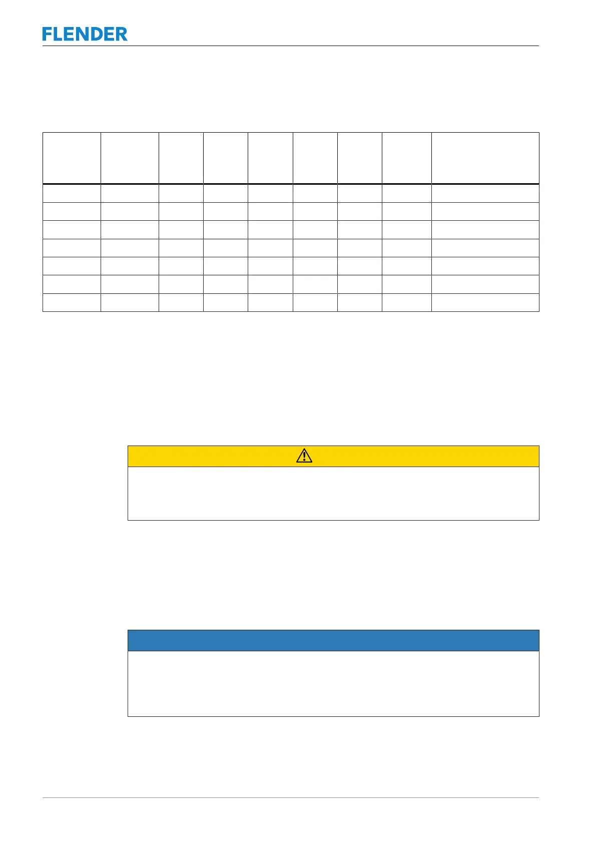
The following table contains the values for the diameter and axial position of the threaded
hole depending on the coupling size.
FLUDEX
Size
N-EUPEX
Size d1 e1
mm
e2
mm
e5
mm
e6
mm
e7
mm
Tightening torque T
A
of the set screws
Nm
370 180 M12 23 16 30 25 85 25
425 200 M12 25 20 40 25 85 25
490 225 M12 25 22 40 30 85 25
565 250 M16 23 24 50 50 85 70
655 315 M16 50 35 60 75 85 70
755 350 M20 40 40 70 75 85 130
887 440 M24 50 60 90 75 85 230
Table5-4: Diameter and axial position of the threaded hole, tightening torque
Apply the specified tightening torques as listed in Section Tightening procedure (Page81).
Position of the threaded hole with respect to the parallel keyway
Position the threaded hole for the set screw on the parallel keyway.
Selection of the set screw
CAUTION
Physical injury
Risk of injury from protruding set screw.
• Please observe the information about selecting the set screw.
Use set screws in accordance with ISO 4029 with a toothed cup point. The size of the set
screw is determined by the bore made. The set screw should fill out the threaded hole as
much as possible and must not protrude beyond the hub.
5.1.4 Balancing the coupling5.1 Preparatory work
NOTICE
Property damage to coupling part 1 (1)
If you completely drill through the base of a flexible element pocket on coupling part 1 (1),
then coupling part 1 (1) is no longer allowed to be used for operation.
• Please observe the stipulations about machining the balancing bore.