Assembly
5.2 Mounting the coupling
M4602-02en Edition 09/2022 37
Information
Coupling parts with cylindrical bore
To make assembly easier, you can heat coupling parts 1 (1), 11 (11), 32 (32) or 120 (120)
with cylindrical bore up to a maximum of 120°C if required. Note the temperature range of
the flexible elements(12) when doing this (see Section N-EUPEX flexible elements (12)
(Page82)) ). Remove the flexible elements (12) if necessary. Protect adjacent compon-
ents against damage and heating to temperatures above 80°C.
5. Secure the coupling parts 1 (1), 11 (11), 32 (32) or 120 (120) with a set screw or an end
plate. When securing with a set screw the shaft must not protrude or be set back from
the inner side of the hub.
6. Tighten up the set screw or the screw to attach the end plate to the specified tightening
torque T
A
(for the set screw please see section Machining an axial locking mechanism
(Page31)).
7. If you have removed the flexible elements (12), reinstall the flexible elements (12).
8. If you have removed coupling part 3 (3), screw coupling part 2 (2) or 13 (13) to coupling
part 3 (3) hand tight.
9. Screw on the coupling part 2 (2) or 13 (13) with the specified tightening torque TA (see
Section Tightening torques and widths A/F (Page80)).
10.Before flanging the main coupling to the hub carrier part (120), clean the interior of the
hub carrier part (120), the associated area of the main coupling, the holder keyways for
the O-rings (117, 138) as well as the centring and flange surfaces from any contamina-
tion.
11.Grease the O-rings (117, 138) and fit them into their holder keyways.
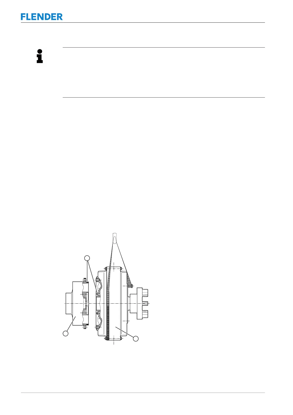
12.Hang the main coupling in suitable hoisting gear to mount the hub carrier part (120).
This ensures that the hub carrier part (120) is placed on the centring shoulder as coaxi-
ally as possible without canting.
Figure5-5:Mounting the coupling parts
① O-rings
② Main coupling
③ Hub carrier part (120)