Maintenance
8.3 Replacing the flexible elements
M4602-02en Edition 09/2022 57
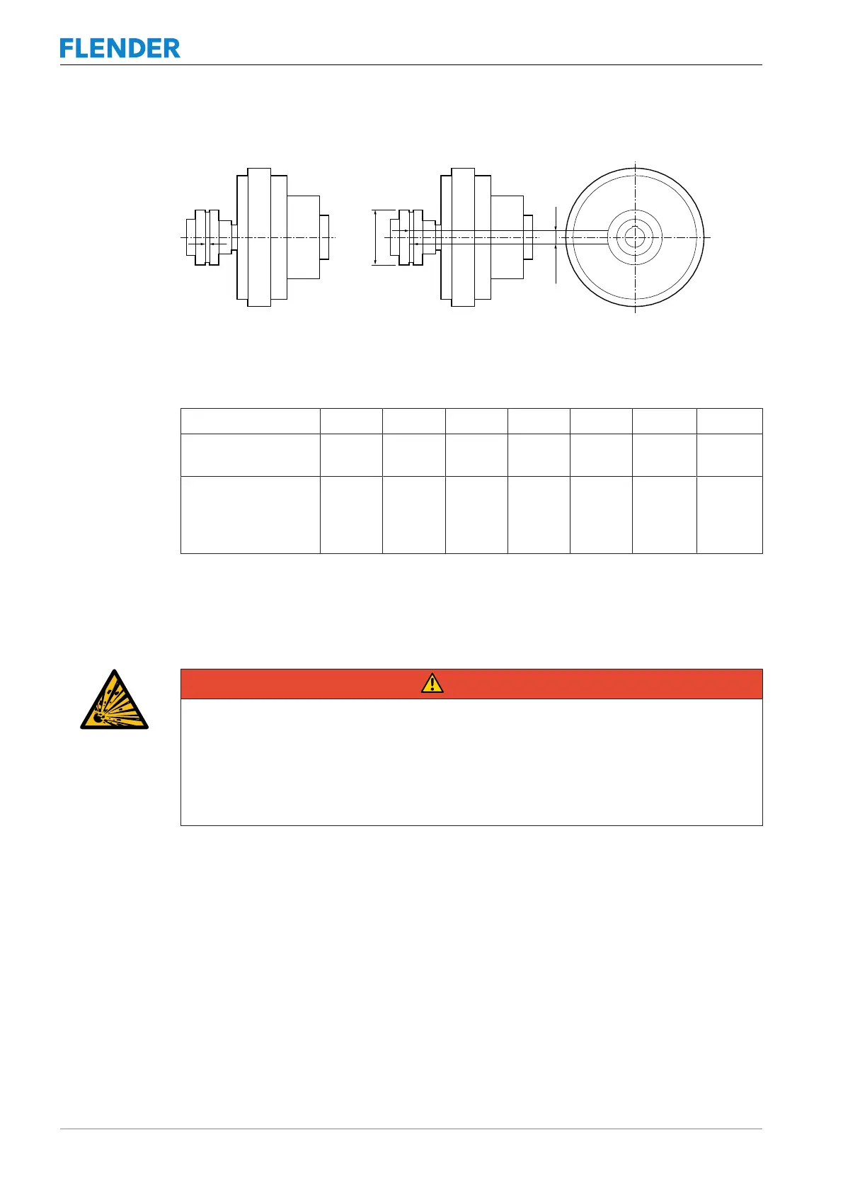
2. Mark both of the coupling halves in the way shown in the diagram below.
Figure8-1:Markings for calculating the torsional backlash
3. Turn the coupling part in the opposite direction up to the stop.
The markings on both halves will then move apart. The distance between the markings
corresponds to the chord dimension ΔS
V
.
FLUDEX size 370 425 490 565 655 755 887
N-EUPEX size
[d
1
]
180 200 225 250 315 350 440
Maximum permiss-
ible torsional back-
lash ΔS
V
[mm]
8.0 8.5 9.0 10.0 10.5 11.5 14.0
Table8-3: Maximum permissible torsional backlash
8.3 Replacing the flexible elements8.3 Replacing the flexible elements
DANGER
Danger due to bursting of the coupling
If you do not observe the information stipulated here regarding replacement of wearing
parts, this can lead to bursting of the coupling during operation. There is a risk of fatal in-
jury from flying fragments. If a coupling bursts in an area at risk of explosion, then this can
result in an explosion.
• Please observe all the stipulations concerning the replacement of wearing parts.
Replace the flexible elements(12) if the maximum permissible torsional backlash has been
reached.
Procedure
The flexible elements (12) can be replaced without moving the coupled machines.
1. Undo the connection between coupling parts 2 (2) and 3 (3).
2. Move the coupling part 3 (3) axially.
The flexible elements (12) are freely accessible after coupling part 2 (2) has been
turned.
3. Remove the flexible elements (12).
4. Install the new flexible elements (12).