Assembly
5.1 Preparatory work
32 Edition 09/2022 M4602-02en
Please consult Flender if you want to use an end plate.
Note the following when using a set screw:
• Diameter and axial position of the threaded hole in the hub
• Position of the threaded hole with respect to the parallel keyway
• Selection of the set screw
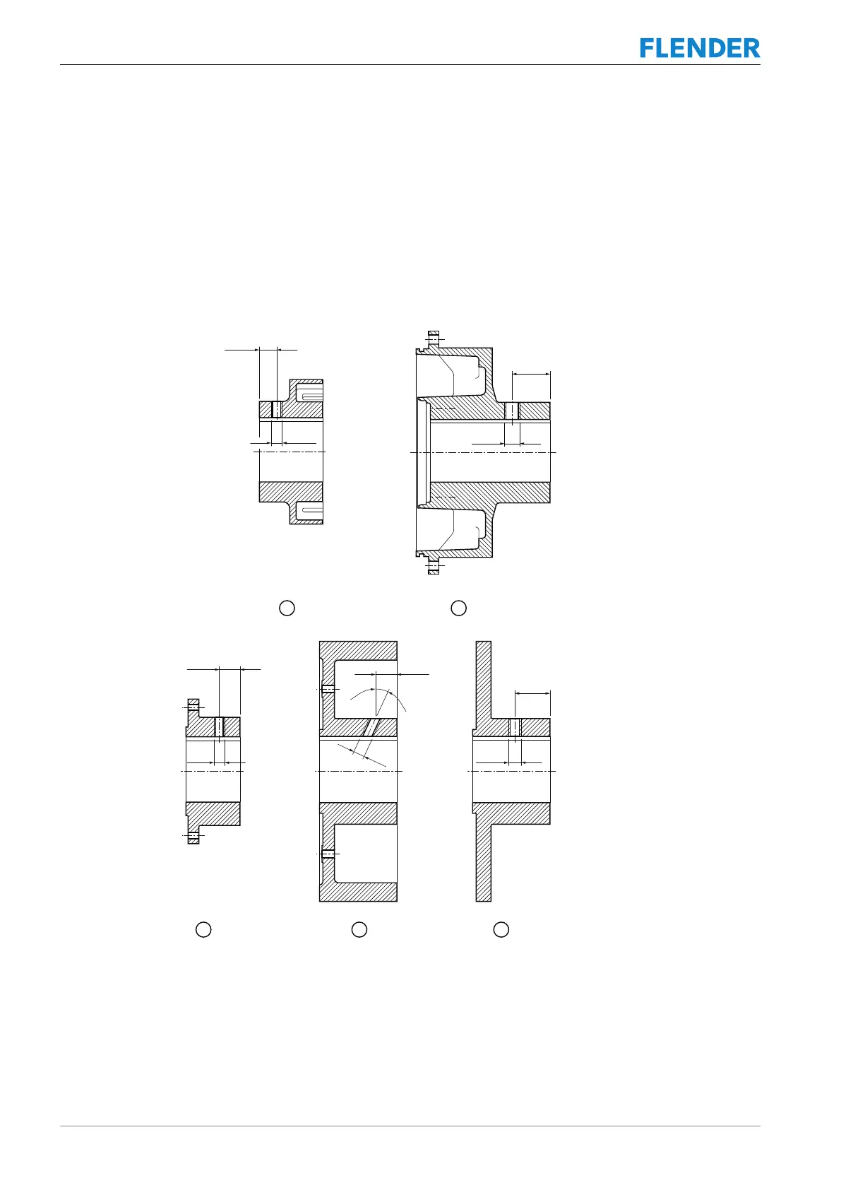
Diameter and axial position of the threaded hole in the hub
The following diagram shows the axial position of the threaded hole:
F
F
E
F
F
E
E
E
p
F
E
Figure5-2:Diameter and axial position of the threaded hole in the hub
① Coupling part 1
② Coupling part 120
③ Coupling part 11
④ Coupling part 32
⑤ Coupling part 32