Description
3.1 Design of the couplings
22 Edition 09/2022 M4602-02en
3.1 Design of the couplings3.1 Design of the couplings
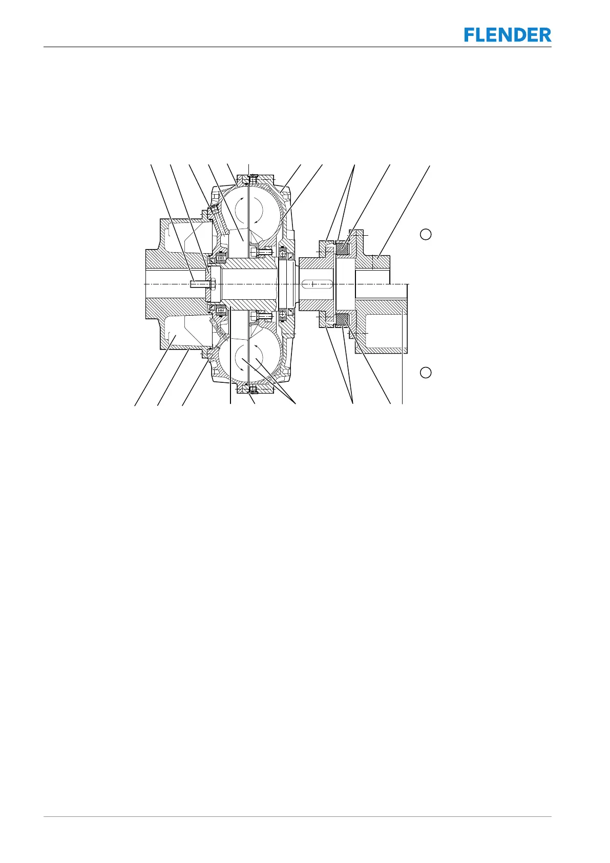
The illustration shows the different types with their components using the types FND and
FNDB as examples.
Figure3-1:General description of series FN
① FND
② FNDB
7 Prechamber
8 Working chamber
9 N-EUPEX add-on coupling
10 Stowage space
11 Part 11
12 Flexible element (N-EUPEX)
32 Part 32
101 Blade shell (outer wheel)
102 Cover
103 Fusible safety plug
105 Bucket wheel (inner wheel)
106 Shaft
120 Hub carrier part (large prechamber)
140 Retaining washer
141 Retaining screw
153 Filling plug
163 Screw plug
173 Prechamber drain plug
The FLUDEX coupling consists of an inner rotor and a housing supported on it. The inner ro-
tor includes the shaft (106) on which the bucket wheel (105) is mounted. The housing in-
cludes the cover (102) and the blade shell (101), which are connected to each other via a
flange bolt connection.