Assembly
5.4 Filling the gear unit with operating fluid
M4602-02en Edition 09/2022 43
As a tool for filling the coupling and for checking the filling level, there are marking lines with
the assigned letters “W” to “Z” cast on the coupling housing in a raised relief. These can be
marked accordingly on the coupling during initial filling with the correct filling quantity and/or
further markings can be added.
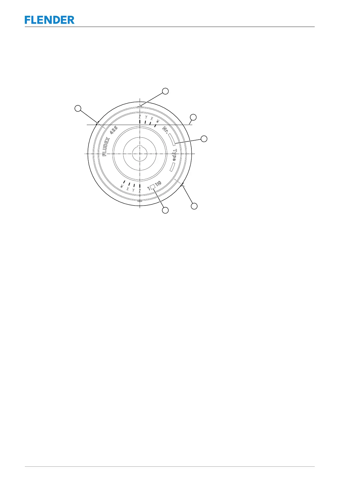
Figure5-7:Filling the coupling
① Filling plug (153)
② Maximum fill level
③ Stamp field for order number
④ Fusible safety plug (103)
⑤ Stamp field for filling quantity
⑥ Screw plug (163) / fusible safety plug (103)
1. When filling and/or checking the fill level, turn the mark with the desired filling quantity to
the highest position (12 o’clock).
For intermediate values, select the appropriate intermediate position.
2. To vent the inner room better, unscrew the screw plug (163) inserted in the outer flange
or the second fusible safety plug (103).
The screw (163 or 103; with size 887 only 163) is arranged in such a way that in events
of overfilling, the excess quantity can drain out there.
3. Take the filling quantities to be assigned to the markings “W”-“Z” from the “Filling quantit-
ies in litres” table below.
4. Fill the operating fluid at the filling plug (153).
Only this filling opening is provided with a filling channel that offers protection against ac-
cidental overfilling. The coupling is filled with the desired quantity when the filling level
reaches the edge of the bore for the screw plug (163) or the fusible safety plug (103).