FLUXUS WD100, WD200 7 Installation of the Transducers
36 UMFLUXUS_F5WDV1-1EN, 2016-04-08
• Insert the long end of the tension strap into the second slot of the tension strap clamp (see Fig. 7.9 a).
• Tighten the tension strap and bend it.
• Bend both ends of the tension strap (see Fig. 7.9 b).
• Repeat the steps for the second tension strap. Position the tension strap at the distance s (see Fig. 7.9).
• Put the rail on the tension strap clamps.
• Use the screws to fix the rail to the tension strap clamps (see Fig. 7.10).
• Tighten the screws.
Installation of the rail with the ratchet clasp
• Cut the tension strap to length (pipe circumference + at least 120 mm).
• Insert approx. 100 mm of the tension strap into parts 1 and 2 of the ratchet clasp (see Fig. 7.11 a).
• Bend the tension strap.
• Insert the tension strap into part 1 of the ratchet clasp (see Fig. 7.11 b).
• Tighten the tension strap.
• Insert the long end of the tension strap into the tension strap clamp and the metal spring (see Fig. 7.12). It is not neces-
sary to mount the metal spring:
– on steel pipes
– on pipes with an outer pipe diameter < 80 mm or
– on pipes that are not subjected to significant temperature fluctuations
• Place the tension strap around the pipe (see Fig. 7.13).
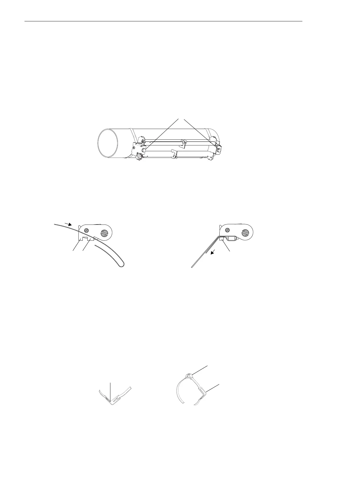
Fig. 7.10: Rail on the pipe
a b
Fig. 7.11: Ratchet clasp with tension strap
Fig. 7.12: Tension strap with the metal spring and the tension strap clamp
tension strap clamp
metal spring