8 Connection FLUXUS WW
UMFLUXUS_WWV1-1EN, 2018-02-28 51
8.1.1.2 Transducer cable with plastic cable jacket and stripped cable ends
• Remove the left blind plug for the connection of the transducer cable (see Fig. 8.3).
• Open the cable gland of the transducer cable. The compression part remains in the cap nut.
• Push the transducer cable through the cap nut and the compression part.
• Prepare the transducer cable.
• Shorten the external shield and brush it back over the compression part.
• Screw the sealing ring side of the basic part tightly into the housing of the transmitter.
• Insert the transducer cable into the housing.
• Fix the cable gland by screwing the cap nut onto the basic part.
• Connect the transducer cable to the terminals of the transmitter (see Fig. 8.1, Fig. 8.3 and Tab. 8.2).
Tab. 8.1: Terminal assignment (transducer cable)
terminal connection
X_AV SMB connector (brown cable, marked white)
X_AR SMB connector (brown cable, marked black)
Attention! Observe the "Safety instructions for the use in explosive atmospheres" (see SIFLUXUS document).
Attention! For good high frequency shielding, it is important to ensure good electrical contact between the exter-
nal shield and the cap nut (and thus to the housing).
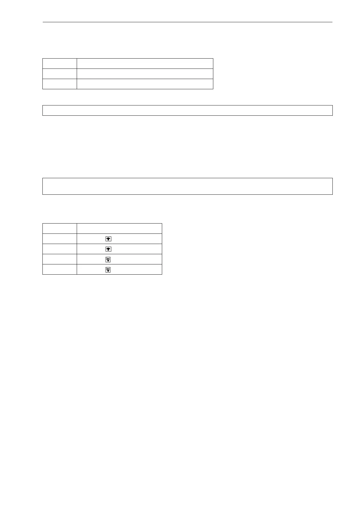
Tab. 8.2: Terminal assignment
terminal connection
AV transducer (core)
AVS transducer (internal shield)
ARS transducer (inner shield)
AR transducer (core)