FLUXUS WW 8 Connection
52 UMFLUXUS_WWV1-1EN, 2018-02-28
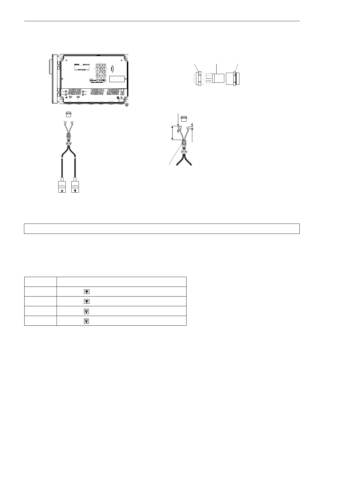
8.1.1.3 Transducer cable with stainless steel conduit and stripped cable ends
• Remove the left blind plug for the connection of the transducer cable (see Fig. 8.4).
• Insert the transducer cable into the housing.
• Fix the transducer cable by tightening the cable gland.
• Connect the transducer cable to the terminals of the transmitter (see Fig. 8.1, Fig. 8.4 and Tab. 8.3).
Fig. 8.3: Connection of the transducer cable with plastic cable jacket and stripped cable ends to the transmitter
Attention! Observe the "Safety instructions for the use in explosive atmospheres" (see SIFLUXUS document).
Tab. 8.3: Terminal assignment (transducer cable)
terminal connection
AV transducer (brown cable, marked white)
AVS transducer (red cable)
ARS transducer (red cable)
AR transducer (brown cable)
AVSAV
AGN
ARS
AR
BVSBV
BGN
BRS
BR
SA1
SA2
SA3
SA4
SB1
SB2
SB3
SB4
T1a
T1b
S2 T2a
T3a
T3b
S4
T4a
T2b
T4b
T1A
T1B
S1 T2A
T3A
T3B
S3
T4A
T2B
T4B
A+
B-
P1+ P2+
P4+
P5a
P6a P7a
P3+
101
103
P1- P2-
P4-
P5b
P6b
P7b
P3-
PE
N(-)
L(+)
U L T R A S O N I C F L O W M E T E R
1 32
0
4 65
7 8
N E X T
Q
O N
Q -
Q +
M U X
D I S P
Q
O F F
9
D I S P
E N T E R
C
B R K
R E S T A R T
I N I T
external shield,
brushed back
cap nut
compression part basic part
70 mm
10 mm
20 mm
cable gland