7 Connection
PIOX R721 7.1 Sensor
33
UMPIOX_F72xV1-3EN, 2021-09-01
7.1.1 Connection of the cable to the sensor
• Loosen the 2 screws on the junction box of the sensor.
• Remove the housing cover.
• Remove the blind plug on the housing cover to connect the sensor cable.
• Open the cable gland of the sensor cable. The compression part remains in the cap nut.
• Insert the sensor cable through the cap nut, the compression part and the basic part.
• Prepare the sensor cable with the cable gland.
• Insert the sensor cable through the housing cover.
• Tighten the gasket ring side of the basic part firmly into the housing cover.
• Connect the sensor cable to the terminals of the transmitter.
Important!
The degree of protection of the transmitter is only ensured if all cables are tightly fitted using cable glands and the
housing is firmly screwed.
Important!
The external shield of the sensor cable must not have any electrical contact to the sensor housing.
Tab. 7.2: Terminal assignment
terminal connection
+ yellow
- green
A+ brown
B- white
S shield
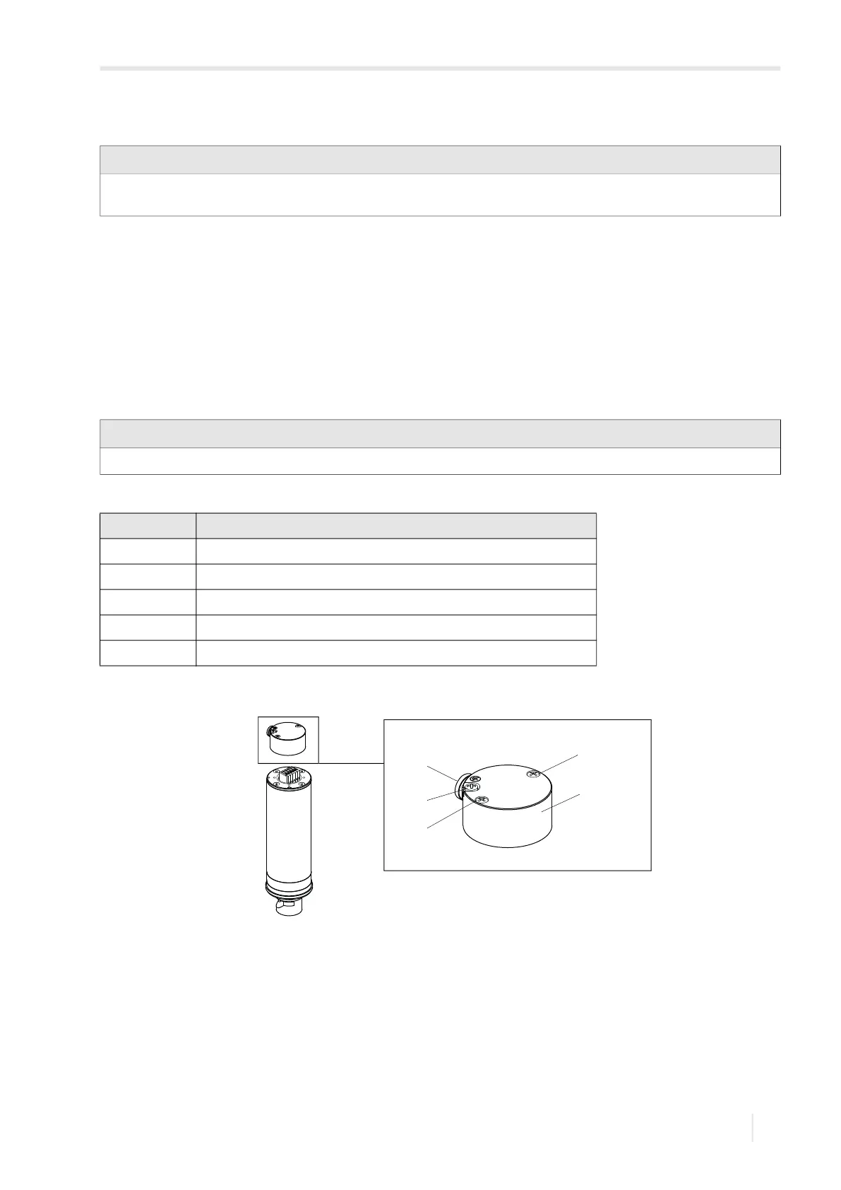
Fig. 7.1. Sensor PIOX R500
1 – equipotential bonding terminal
2 – blind plug
3 – screws
4 – housing cover
1
2
3
4
3