7 Connection
7.1 Sensor PIOX R721
2021-09-01, UMPIOX_F72xV1-3EN
34
• Position the housing cover with the screws on the holes. Observe the orientation of the cable entries on the housing
cover.
• Tighten the screws.
• Fix the cable gland by screwing the cap nut onto the basic part.
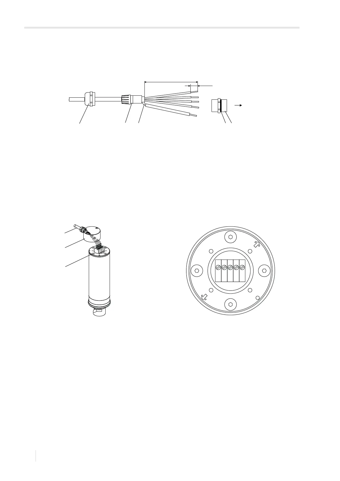
Fig. 7.2: Preparation of the sensor cable
1 – cap nut
2 – compression part
3 – basic part
4 – gasket ring side of the basic part
5 – external shield
Fig. 7.3: Connection of the sensor cable and terminal strip
1 – sensor cable
2 – housing cover
3 – hole
1
sensor
70 mm
8 mm
2
3
45
2
1
3