7 Connection
7.5 Service interfaces PIOX R721
2021-09-01, UMPIOX_F72xV1-3EN
44
• Push the cable through cap nut, compression part, basic part and sealing ring (sealing ring: only for cable gland M20, not
for cable gland 1/2 NPS).
• Insert the cable into the housing of the transmitter.
• Push the cable through the ferrite nut.
• Prepare the cable (see the documentation provided by the manufacturer).
• Install the connector (see the documentation provided by the manufacturer).
• Insert the connector into the LAN interface.
• Position the cable in the housing as shown in Fig. 7.12.
• Fix the cable gland by screwing the cap nut onto the basic part.
• Fix the sensor cable by tightening the cable gland with the ferrite nut.
Transmitter with aluminum housing
• Remove the blind plug to connect the cable to the transmitter.
• Open the cable gland of the LAN cable. The compression part remains in the cap nut.
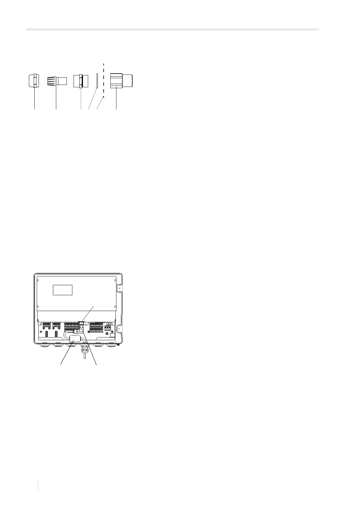
Fig. 7.13: Cable gland
1 – cap nut
2 – compression part
3 – basic part
4 – sealing ring (only for cable gland M20, not for cable gland 1/2 NPS)
5 – housing wall
6 – ferrite nut
Fig. 7.14: Connection of the LAN cable
1 – LAN interface
2 – foldable ferrite core
3 – LAN connector
21 3 4 5 6
2
1
3