PIOX S70x 7 Connection
70 UMPIOX_S7V4-6-3EN, 2018-10-10
7.2.3.1 Connection to the Transmitter
PIOX S704
• Remove the second blind plug on the right for the connection of the extension cable (see Fig. 7.24).
• Open the cable gland of the extension cable. The compression part remains in the cap nut (see Fig. 7.25 and Tab. 7.12).
• Push the extension cable through the cap nut, the compression part, the basic part, and the reducer.
• Prepare the extension cable.
• Insert the extension cable into the housing.
• Screw the gasket ring side of the reducer tightly into the housing of the transmitter.
• Tightly screw the basic part into the reducer.
• Fix the cable gland by screwing the cap nut onto the basic part.
• Connect the extension cable to the terminals of the transmitter (see Fig. 7.1, Fig. 7.24 and Tab. 7.15).
PIOX S705
• Remove the second blind plug on the right for the connection of the extension cable (see Fig. 7.26).
• Open the cable gland of the extension cable. The compression part remains in the cap nut (see Fig. 7.27 and Tab. 7.12).
• Push the extension cable through the cap nut, the compression part, the basic part, the reducer and the gasket ring.
(Sealing ring: only for cable gland M20, not for cable gland 1/2 NPS.)
• Prepare the extension cable.
• Insert the extension cable into the housing.
• Tightly screw the basic part into the reducer.
• Fix the cable gland by screwing the cap nut onto the basic part.
• Fix the extension cable by tightening the cable gland with the counter nut with the ferrite nut.
• Connect the extension cable to the terminals of the transmitter (see Fig. 7.2, Fig. 7.26 and Tab. 7.15).
PIOX S709
• Prepare the extension cable (see Fig. 7.30).
• Connect the extension cable to the terminals of the transmitter (see Fig. 7.3, Fig. 7.29 and Tab. 7.15).
7.2.3.2 Connection to the Junction Box
Extension cable
• Remove the blind plug in the middle for the connection of extension cable (see Fig. 7.33).
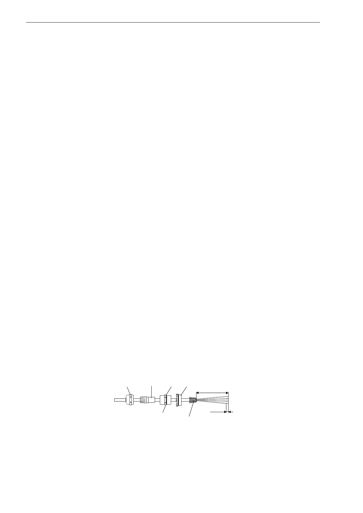
• Open the cable gland of the extension cable (see Fig. 7.32 and Tab. 7.12). The compression part remains in the cap nut.
• Push the extension cable through the cap nut and the compression part.
• Prepare the extension cable.
• Cut the external shield and brush it back over the compression part.
• Screw the gasket ring side of the reducer into the junction box (see Fig. 7.32).
• Tightly screw the basic part into the reducer.
• Insert the extension cable into the junction box.
• Fix the cable gland by screwing the cap nut onto the basic part.
• Connect the extension cable to the terminals of the transmitter (see Fig. 7.33 and Tab. 7.16).
Fig. 7.32: Preparation
cap nut
compression
part
basic part
reducer
gasket ring side
110 mm
7 mm
external shield,
brushed back

 Loading...


