Section 4: Using the Model 9100: DC Current Function 4.5-9
Final Width = 215mm
4.5.6.2 'AUXILIARY OUTPUT'
'
AUX OUTPUT' is the second key from the top. This allows access to a guarded I+ output
to the UUT, from the 15-way D-Type socket underneath the front terminals, instead of
using the main I+ terminal. Where such guarding is required, any external guard screen
for I+ should also be connected to the socket. The UUT I- connection must always be
returned to the main I- terminal.
DC Current I+ is output via pin 8 of the D-Type socket, with a provision to guard I+ by
connecting an external guard screen to pin 7 of the socket. The UUT I- or Lo must be
returned via the main I- terminal.
To protect internal wiring, the maximum (-20A to +20A) span of DC Currents is not
available from these pins. The guarded output is limited to a span of -1A to +1A.
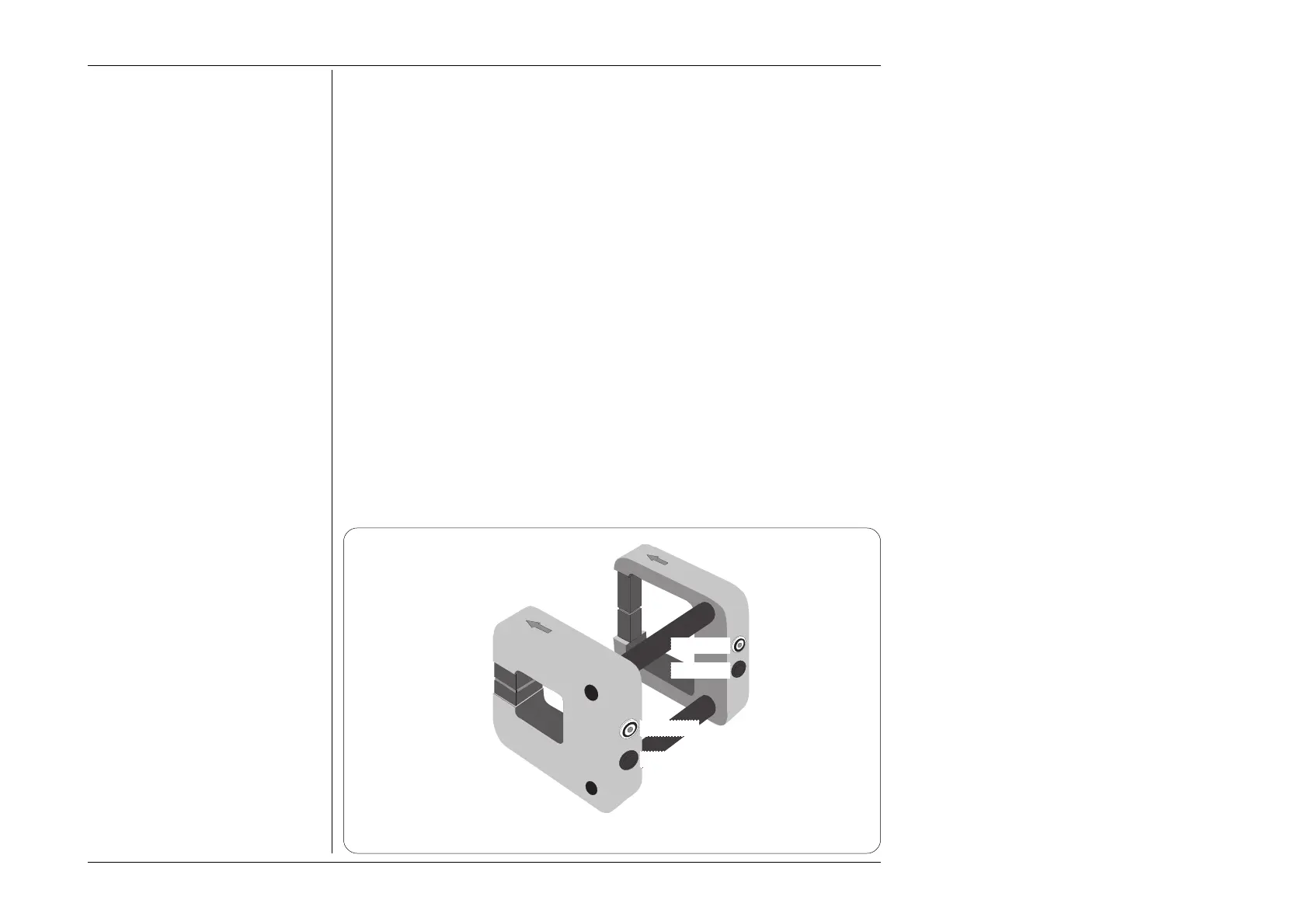
4.5.6.3 10- and 50-Turn Current Coils (Option 200)
(Fig. 4.6.1)
Option 200 comprises two coils for use with current clamps or clamp-on ammeters.
Effective current step-up ratios of X10 and X 50 are selected by connections to the 10-
turn and 50-turn primaries. The 9100 I+ connects to either a '10 TURN' or a '50 TURN'
terminal, and the I- terminal is connected to the 'COMMON' terminal on the same coil.
The sensor clamp passes through the center air space of the selected coil — manufacturers'
precautions should be observed as to the positioning of the clamp within the coil — refer
also to the notes with Fig 4.5.4/5/6 on page 4.5-14.
Fig. 4.5.1 Option 200 — 10- and 50- Turn Coil Assembly — General View
CURRENT
COIL
X 50
50 TURN
10 TURN
COMMON
COMMON
 Loading...


