Section 4: Using the Model 9100: Thermocouple Function 4.14-7
Final Width = 215mm
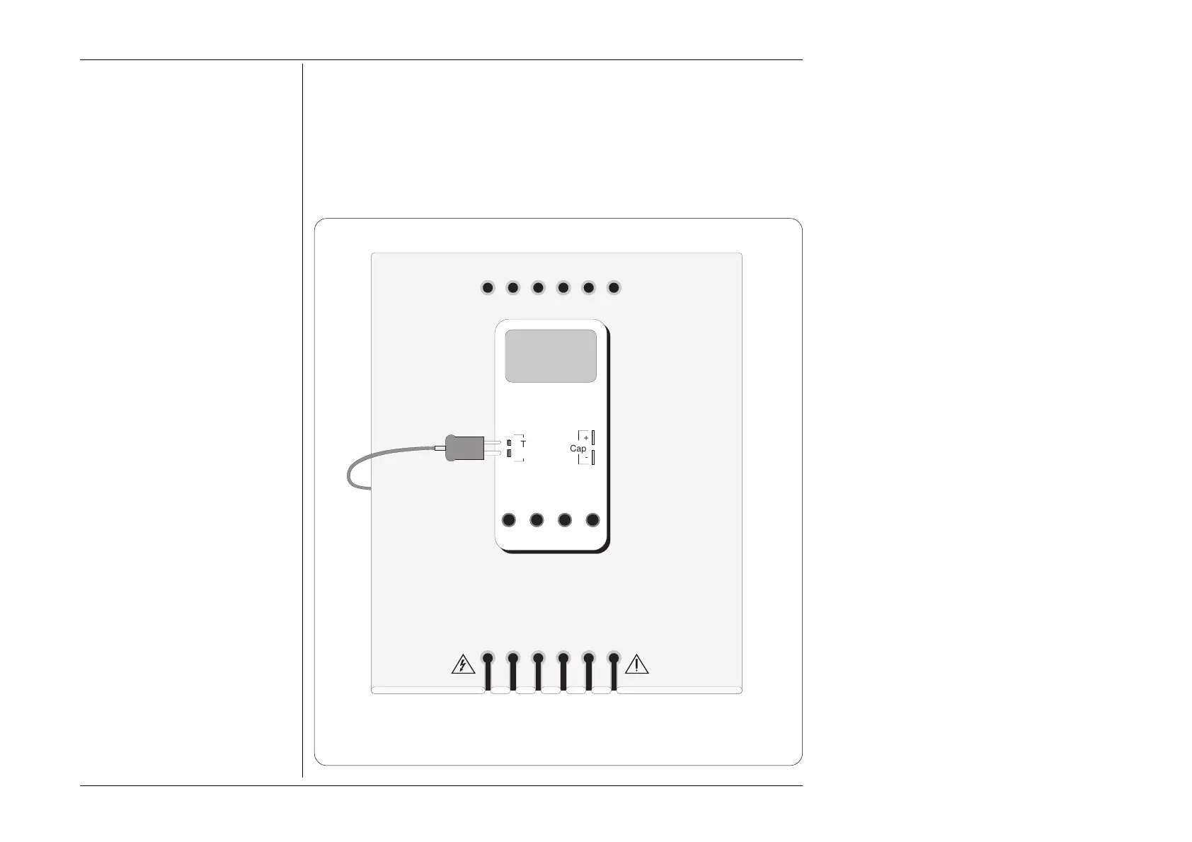
Fig. 4.14.2 Interconnections for Thermocouple UUT Calibration
(Leads which are not shown are not connected)
4.14.7 Thermocouple Routines for Calibrating UUTs
4.14.7.1 Interconnections
The general connection scheme for UUT calibration is illustrated in Fig. 4.14.2. Always
use the correct extension cable from the thermocouple socket on the isothermal block to
the UUT thermocouple input. Observe the correct polarity, otherwise spurious junctions
may be set up.
10A mA COM V-
Cap
+
-
Thermo
Couple
+
-
+
Connect both ends in
correct orientation;
The 2mm blade is the
'+' contact.
On most UUTs, the
plug/socket
connection is unique
and cannot be
wrongly connected
Always use the correct
thermal extension
connector from the
isothermal block
I+mAI+ 20ALI-sLsHH
WhiYellBlkBlkRedRed
Adaptor Parking Holes
Work Mat
UUT