Section 4: Using the Model 9100: RTD Temperature Function 4.15-5
Final Width = 215mm
4.15.4 Delivery of Resistance Simulation of RTD Sensor
4.15.4.1 Simulation Drive
The simulation is available only through the main front panel
terminals. Correct interconnections must be used to maintain
traceability. It is assumed that the UUT will measure resistance
directly.
4.15.4.2 Simulation Analog
The RTD sensor is inherently non-linear, and sensor
thermometers incorporate circuitry or software to permit linear
temperature scales to be used. The 9100 is therefore required to
simulate the RTD non-linearity in order to test the UUT.
The temperature set on the 9100 front panel screen is ultimately
converted to a compensated output resistance. For each type of
RTD sensor, a formula is embedded in firmware. This formula
converts the temperature setting into a resistance demand, based
on the published non-linear characteristics of the RTD sensor.
The output resolution of 0.01°C is obtained through that formula.
4.15.4.3 Configuration for RTD Temperature
Measurement in UUTs
Instruments which measure resistance, generally use a method
which drives a 'pseudo-constant' current (Ir) through the
Resistance-Temperature Detector (RTD — often a platinum-
resistance thermometer element), measuring the voltage (Vr)
developed across it. Internal circuits then calculate the resistance
digitally, using a form of Ohm's Law:
R = V/I
Subsequent calculations use the published non-linear
characteristics of the RTD sensor to convert the measured
resistance value into a temperature value.
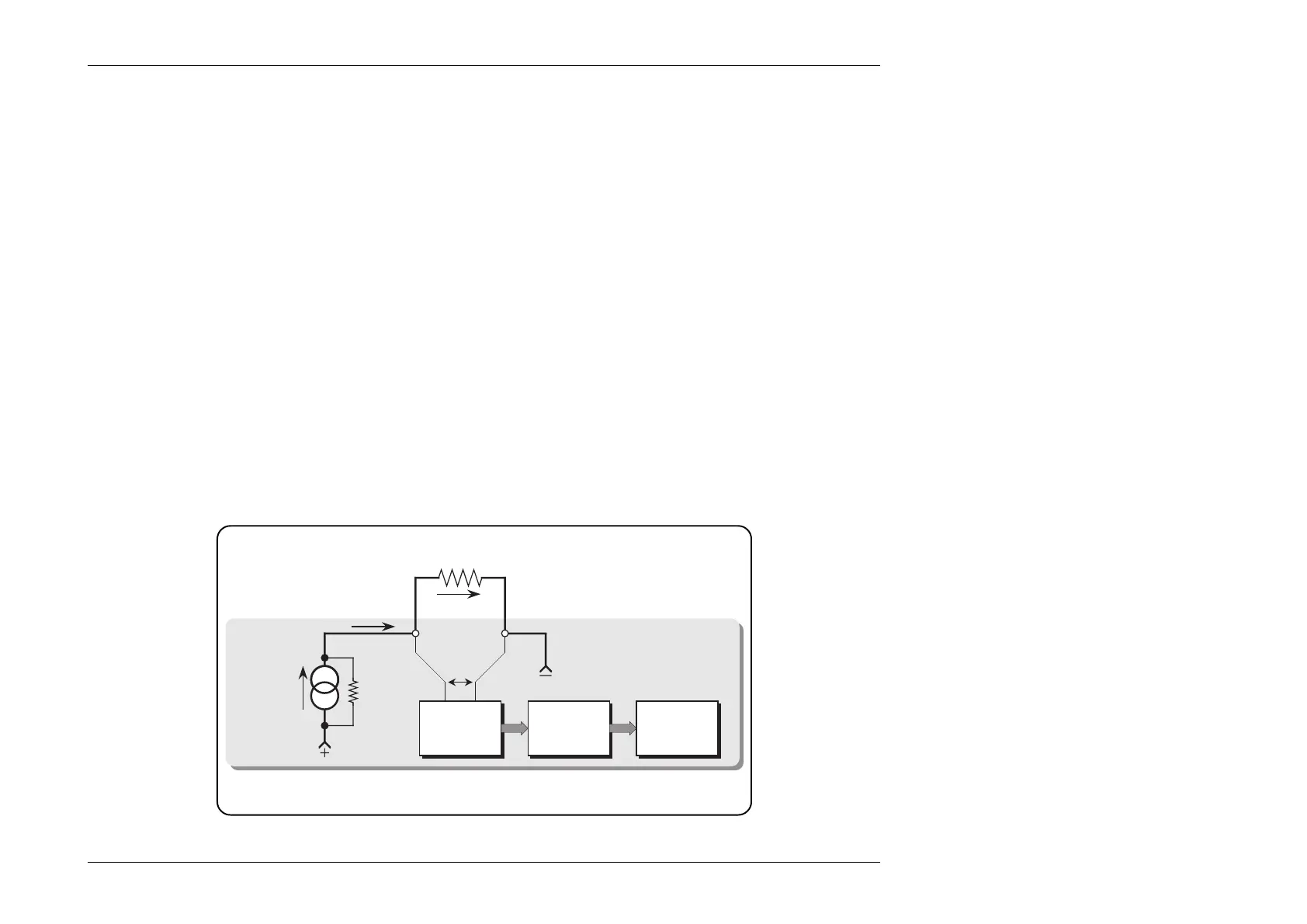
The 9100 assumes that this form of measurement is employed by
the UUT. A simplified illustration is shown in Fig. 4.15.1:
Note that because Ir passes through external test leads connecting
the resistor to the terminals, the voltage sensed across the
terminals will include the lead volts drops, so the result here will
also include the resistance of the UUT's external leads.
Fig. 4.15.1 UUT Configuration for RTD Temperature Measurement
UUT
Test RTD
Resistance
I
r
Voltage
Measurement
Resistance
Calculation
Pseudo
Constant
Current
Source
V
r
°C Com
Resistance-
Temperature
Conversion
and Display