4.16-4 Section 4: Using the Model 9100: Logic-Pulses Function
Final Width = 215mm
Help Available!
Section 3 Editing Tutorials.
4.16.4.1
'Pulse Width' and 'Repetition' Time-Intervals
Pulse width and repetition time-intervals can be changed using 'Digit' and 'Direct' edit
facilities as described in Section 3. On the 'Logic-Pulse' menu screen (illustrated on page
4.16-2) the 'Repetition' time-interval is placed beneath the 'Pulse Width' time-interval in
the center of the screen, as indicated by the icons on the left.
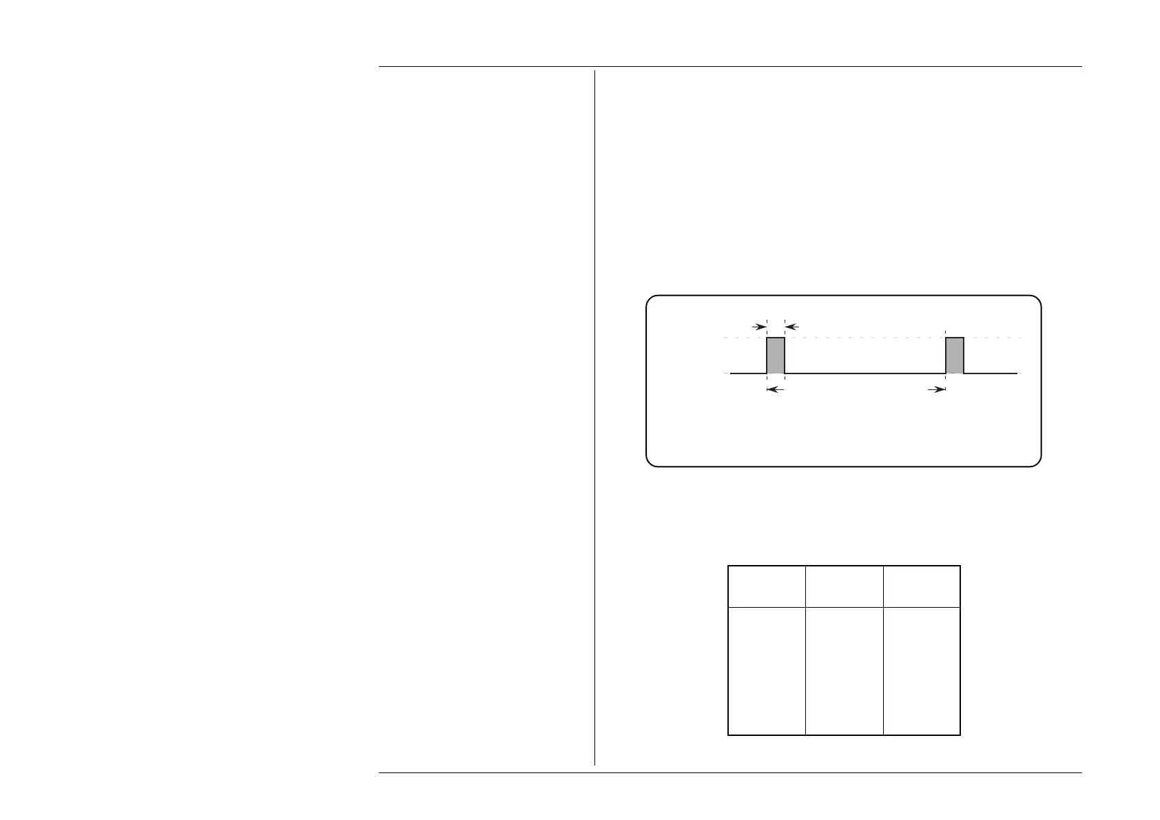
Default Output Waveshape
The default output (TTL levels) is a continuous stream of 1ms-wide positive pulses at a
repetition interval of 10ms — equating to a 1:10 mark/period ratio; 1:9 mark/space ratio;
i.e. 10% duty cycle at 100 pulses per second (pps) — with fixed switching levels, as shown
below in Fig 4.16.1:
4.16.4 Value Editing
Effect of Selecting TTL, CMOS and ECL
Selecting between TTL, CMOS and ECL will only alter the high and low switching levels,
shown in the table below. The selected pulse width and repetition interval will remain the
same.
Selected Signal Voltage
Logic Level
TTL High +5.00 V
Low 0.00 V
CMOS High +5.00 V
Low 0.00 V
ECL High -0.90 V
Low -1.75 V
Fig. 4.16.1 Logic-Pulses Function —
Default Output Waveshape (TTL)
Pulse Width = 1ms
Space = 9ms
Repetition Interval = 10ms
Repetition Rate = 100pps
High Level
= +5V
Low Level
= 0V
 Loading...


