4.17-4 Section 4: Using the Model 9100: Logic-Levels Function
Final Width = 215mm
Help Available!
Section 3 Editing Tutorials.
4.17.4.1
DC Voltage Values
DC Voltage values can be changed using 'Digit' and 'Direct' edit facilities as described in
Section 3. On the '1/Ø' menu screen (illustrated on page 4.17-2), the current DC Voltage
value is placed at the center of the screen.
High/Intermediate/Low Level Indications
An indication of high, intermediate, or low level value is placed beneath the current DC
Voltage value.
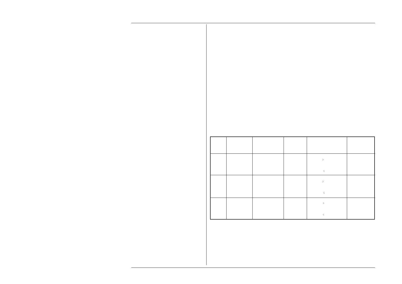
As the DC Voltage value is adjusted, this level indication will change as the value passes
across recognized boundaries within the currently-selected type of logic. These boundaries
are given in the table below, which also shows the screen indications.
Upper Adjustment Limits
The output DC Voltage signal value can be adjusted between the High and Low default
levels; and for TTL and CMOS can be set more positive than the High default level, but
not more negative than the Low default level. The default levels and Upper Adjustment
Limits are also given in the table below.
4.17.4 Value Editing
Logic Signal Screen Default Boundaries Adjustment
Type Level Indication Value Limits
('H' or 'L')
TTL High HIGH LVL +5.00V V
+2.00V 5.50V
Intermediate — — — — --- +0.80V
< V < +2.00V ---
Low LOW LVL 0.00V * V
0.80V 0.00V
CMOS High HIGH LVL +5.00V V
+3.50V 6.00V
Intermediate — — — — --- +1.50V
< V < +3.50V ---
Low LOW LVL 0.00V * V
1.50V 0.00V
ECL High HIGH LVL -0.9V * V
-1.11V 0.00V
Intermediate — — — — --- -1.48V
< V < -1.11V ---
Low LOW LVL -1.75V V -1.48V -5.20V
* indicates the default value on selection of that logic family.