Section 4: Using the Model 9100: AC Harmonics Function 4.21-11
Final Width = 215mm
4.21.7 AC Harmonics Routines for Calibrating UUTs
4.21.7.1 Interconnections
The general connection scheme for ‘UUT calibration of AC Harmonics Functions is as
follows:-
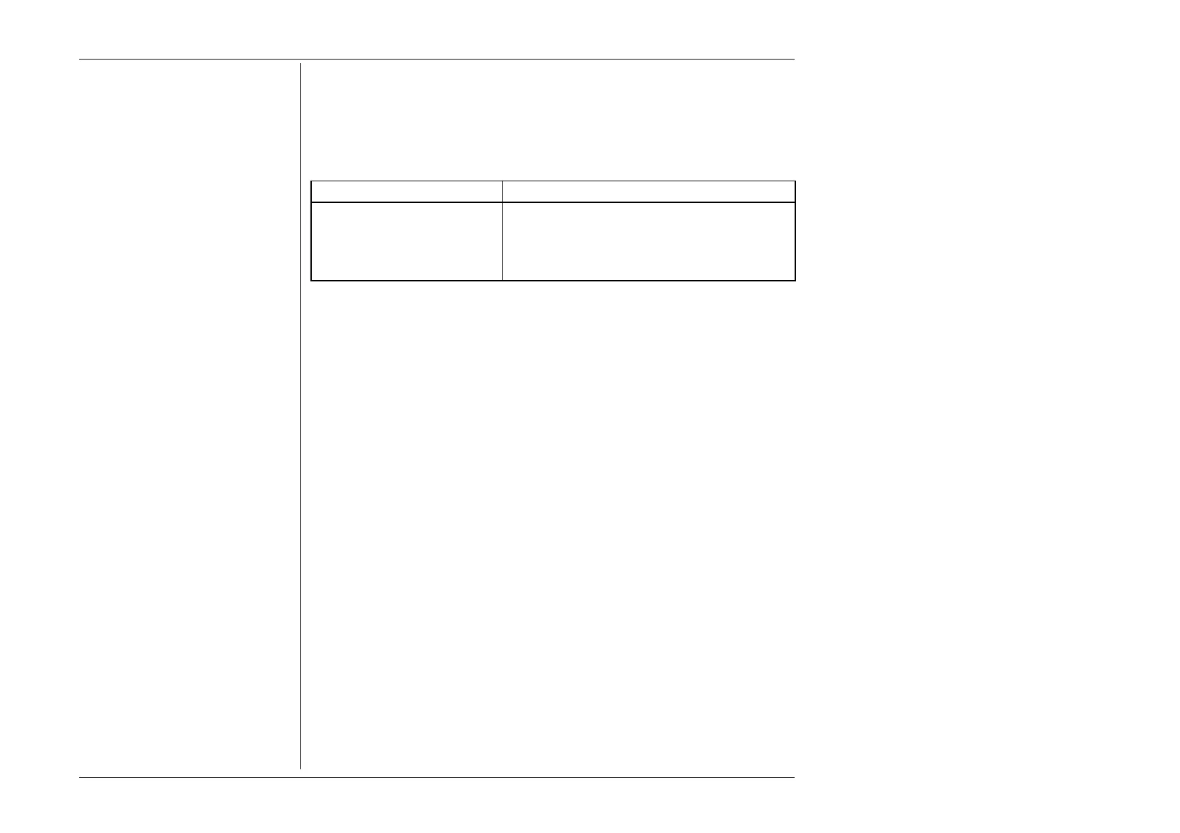
From 9100 To UUT
Hi (Fundamental) Hi
Lo (Fundamental) Lo
I+ (Also sources Aux Voltage) I+ Terminal or Second Channel +ve
I- (Also sources Aux Voltage) I- Terminal or Second channel -ve.
For UUTs without safety banana sockets, use appropriate adaptors.
Note that the 9105 lead set is NOT suitable. Use of this will cause an error if a Current
output is selected. A suitable lead set is supplied with the Power Option. No electrical
connection is possible between Voltage and Current channels of the 9100. This is not
usually a limitation as power meters are almost universally equipped with isolated volts
and current channels.
The detail of the required connections is dependent on the nature of the UUT and its
associated current transducer if any.
4.21.7.2. Using the 9100 as a Fixed source
The following procedure assumes that the instrument is in Manual Mode. In the case of
difficulty, re-read sub-section 3.3.1. Familiarity with the methods of editing screen values
is also assumed (Section 3).
Calibration Setup
1. Connections Connect the 9100 to the UUT, and ensure that both instruments are
powered ON and warmed up.
2. UUT Select AC Harmonics function.
3. 9100 Ensure that the 9100 is in AC Harmonics Function with Output
OFF.