4.2-4 Section 4: Using the Model 9100: Interconnections
Final Width = 215mm
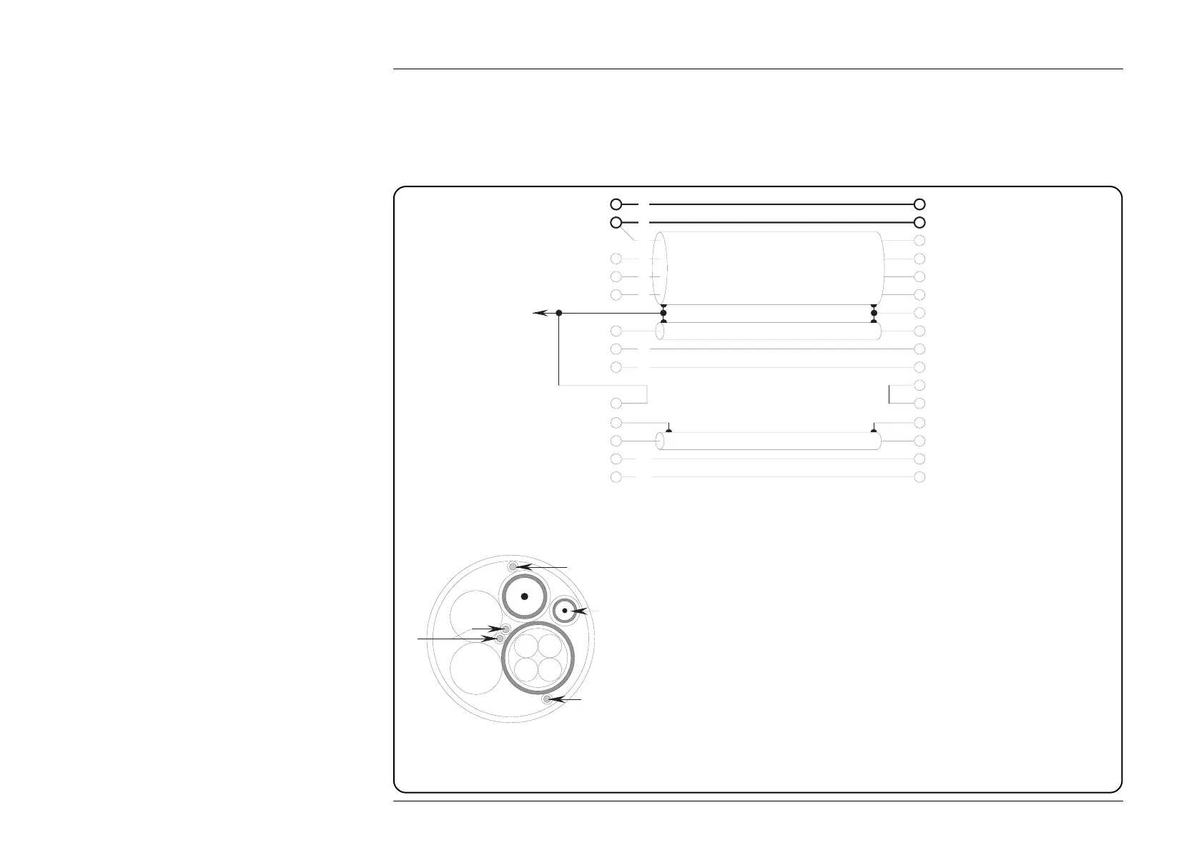
4.2.4 Lead Types when the 9105 is not Used
If it is decided not to use the 9105, reductions in the degradation of specification can still be achieved, using appropriate connections
on short leads of the correct type. To assist in this, Fig. 4.2.3 shows the internal connections in the 9105, and the cross section of
the 9105 main cable shows how the leads are laid out. The lead types are also described.
Fig. 4.2.3 Circuit of 9105 Lead Set, with Main Cable Cross-Section
9100 EndWorkmat End
To metal
core of
Work Mat
I+
I-
Lo
sLo
Hi
sHi
D-7
D-8
D-4
D-5
D-11
D-12
I+20A
LI-
sL
H
sH
I+mA
D-4
D-5
A
A
A
A
D
D
B
C
C
D-12
D-14
D-10
D-9
D-15
E
F
F
D-14
D-10
D-9
D-15
9105 Lead Types
A Four cores 19/0.15mm SPC PTFE insulated Type C (1000V rms)
Inner jacket PTFE Type C (1000V rms) 0.4mm thick
Braid 1/0.1 SPC 85% min coverage
Capacitance of one core to other cores and screen commoned together <80pF/m
B Coaxial 7/0.2 SPC expanded PTFE insulated <60pF/m
Braid 1/0.1 SPC 85% min coverage
Jacket FEP Type A (250V rms)
C Two silver-plated copper cores 7/0.2 Type B PTFE insulated.
D Two cores 651/0.07 (2.5 sq mm) PVC double insulated 1000V rms.
('Multi-Contact' part no: 22.0130-2 Blue, 22.0130-5 Yellow)
E Screened single silver-plated copper core 7/0.2 Type B PTFE insulated.
F Two silver-plated copper cores 7/0.2 Type B PTFE insulated.
D
D
B
AA
AA
C
E
F
F