Section 4: Using the Model 9100: Interconnections 4.2-3
Final Width = 215mm
4.2.3.2 Work Mat Facilities
Layout and Connections
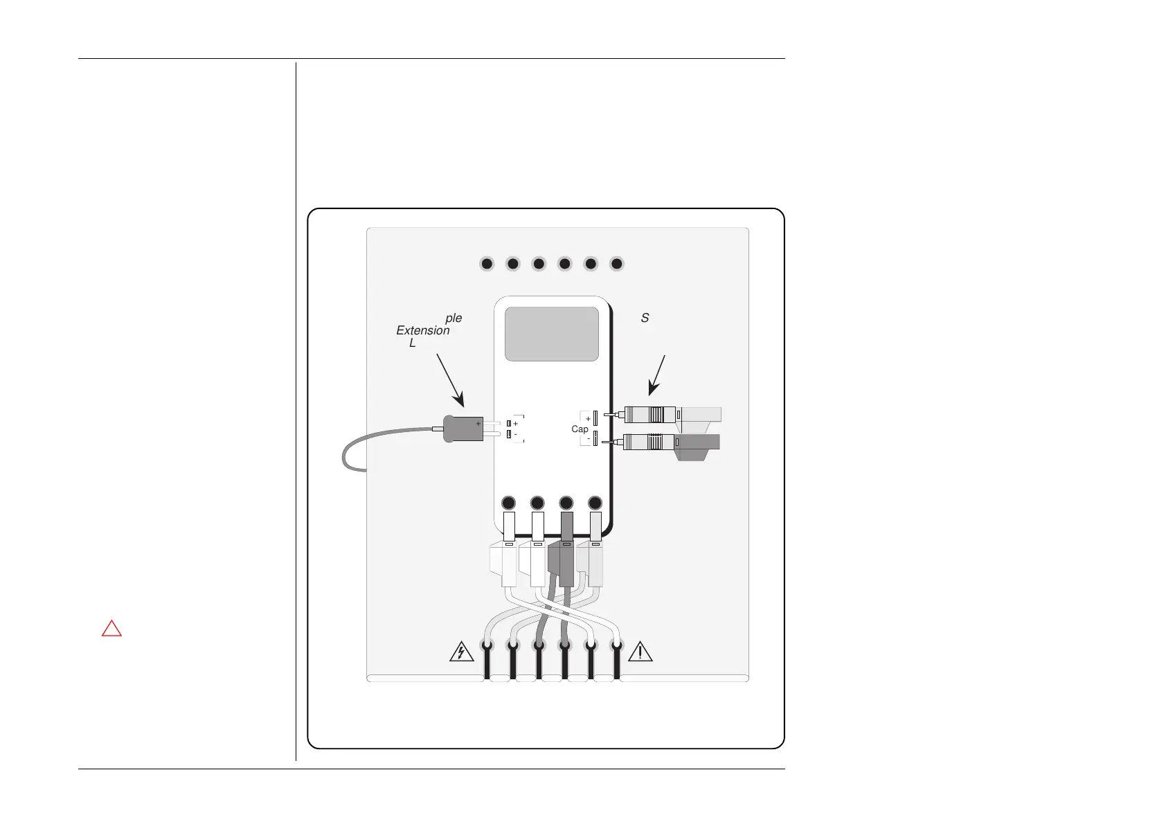
The layout of the 9105 Work Mat is shown in Fig 4.2.2. The connecting leads would not
all be connected at the same time, but the relevant connections for each Function (ACV,
DCI, thermocouple etc.) are given with the procedures for individual functions in the
corresponding sub-sections of Section 4.
Fig. 4.2.2 Layout of 9105 Work Mat
Thermo
Couple
10A mA COM V-
Cap
+
-
+
-
+
Safety Bananas
Terminated with
Probe Adaptors.
A
Thermocouple
Extension
Lead
I+mAI+ 20ALI-sLsHH
WhiYellBlkBlkRedRed
Adaptor Parking Holes
Work Mat
UUT
Caution:
The
!
symbol, shown on elements of
the 9105 leadset, draws attention to
information contained in this handbook
regarding maximum output voltages
and currents.
For details, refer to Volume 2 of this
handbook: Section 7 — Specifications;
page 7-1.