Then the following screen will display:
F1 F2 F3 F4
Enter the value for the 4mA and press OK (F4).
NOTE! 4mA is normally set to 0.
The following menu item allows the user to select an alarm level on the 4-20mA output when a
serious issue is detected that is preventing the calculation of a correct ow value
The options are:
• mA Fault=3.6 mA (Force the 4-20mA signal to 3.6mA on alarm)
• mA Fault=21 mA (Force the 4-20mA signal to 21mA on alarm)
• mA Fault=Not use (4-20mA signal alarm fault not used)
CAUTION! When using the 4-20mA output to control equipment in a failsafe application, use
the wiring conguration and set the Pulse/Alarm Output to System alarm as shown in "Alarm
Output" on p. 58.
After setting the 4mA output value, choose the mA fault value:
F1 F2 F3 F4
The following events will set the output to 3.6mA or 21mA if the alarm level is selected:
• Sensor resistance above high limit
• Bridge Shutdown
When the 4-20mA output is wired through the System Alarm, the following cause the output to go to
0mA:
• Power to the Microprocessor is lost
• Sensor or electronics failure
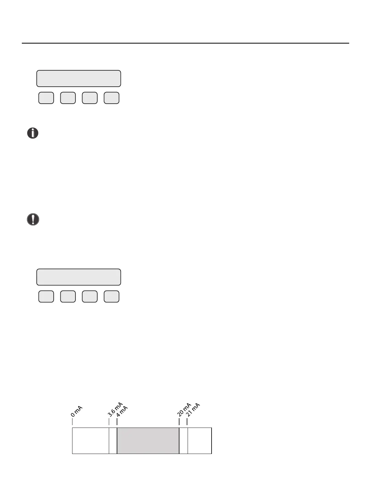
Fig. 4.3: Range of 4-20mA Output and NAMUR Alarm
4 mA = 0 SCFM
CHG OK
mA Fault = Not use
NXT OK
NAMUR
Alarm
Range
NAMUR
Alarm
Range
Working Range
Normal Operation
Operation | 55
Model FT3
Operation