PV series Solar Pumping Inverter
- 12 -
Tank
The water
level sensor
PV panels
Q1
R/L1
S/L2
T/L3
+24V
DI1
DI2
DI3
DI4
DI5
DI6
+10V
AI1
AI2
GND
PE
U/T1
V/T2
W/T3
485+
485-
GND
R1A
R1B
R1C
RUN/STOP
M
(-) (+) PB
PV200
Operation panel
Y2/HO
PLC
DI7/HI
COM
AI3
AO1
GND
+24V
Y1
AO2
GND
R2A
R2B
R2C
+
-
Short film
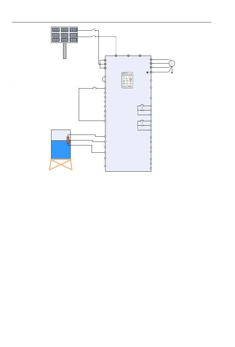
Note: if it is connected to the power or
generator, the terminal short films
between R/S/T must be removed, or
will cause the fires, and even
casualties risk
Short film
Figure 2-2 PV Cell Power Supply Wiring Diagram 2
1. Please wirings as Figure 2-1 or Figure 2-2 according to different inverter powers, check and confirm
the wirings to be correct, and then close Q1.
2. Setting the Motor Parameters
Setting the parameter of name plate on motor F08.01~F08.05。
3. Testing the water yield of pump
Press the operation key “RUN”, under normal circumstance of light strength, if the operation
frequency low or water yield less, which means the motor wiring may be reversed, please exchange
two wirings of motor.
4. System Effluent Speed PI Regulating
If the user has a high requirements for the effluent speed, PI parameters can be regulated
appropriately(H00.09~H00.10), the larger PI parameter, the stronger affection, the faster effluent,
but the larger fluctuation of motor frequency; Otherwise, the slower water effluent, the more steady
frequency of motor operation.
5. MPPT Tracing Speed Commissioning
H00.04 and H00.05 are respectively the lowest voltage and highest voltage under the MPPT mode,
the smaller the range between them two, the faster tracing the maximum power, but the premise if
that the bus voltage during normal operation must fall within this range, or the maximum power point
may not be tracked. Generally speaking, the factory default value is OK.
 Loading...