PV series Solar Pumping Inverter
- 13 -
6. Setting of fault point and fault delay reset time
If clients need to use the pre-warning of weak light, water-logged, under-load, failure monitoring
point, delay time and reset time, water-logged/controlled function can be set as H00.15~H00.19 on
demand; under-load function set as H00.20~H00.22; weak light function set as H00.13~H00.14.
Users also can adopt the default value.
7. Parameter setting after the system operation normally
When the water yield is normal, and system run steadily, the commissioning will be finished. And
then setting F02.00=1, change to terminal operation mode, setting failure auto reset times
F11.27=5.
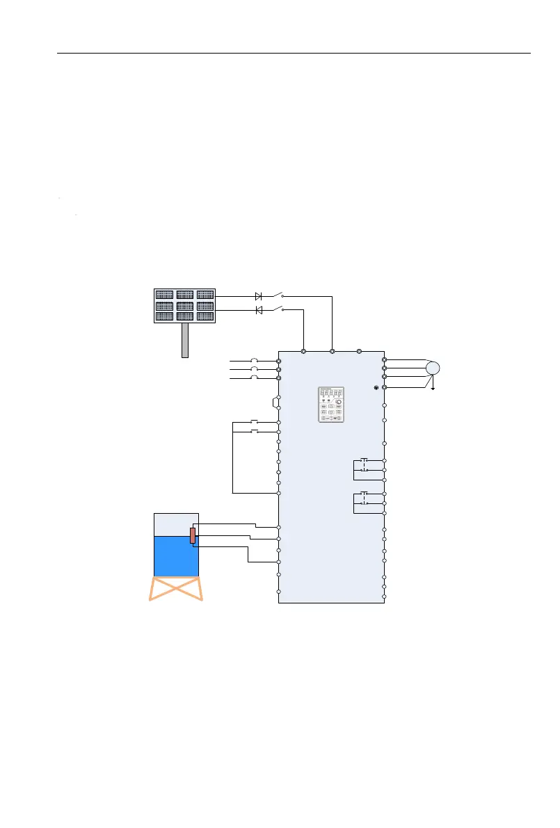
2.2 Grid or Generator power supply wirings
Wiring drawings of below inverters shown as Figure 2-3: PV100 series, PV200 series 3 phase
220V inverters with power lower than 15kw and 3 phase 380V inverters with power lower than 30kw.
Q1
R/L1
S/L2
T/L3
+24V
DI1
DI2
DI3
DI4
DI5
DI6
+10V
AI1
AI2
GND
PE
U/T1
V/T2
W/T3
485+
485-
GND
R1A
R1B
R1C
Q2
M
(-) (+) PB
PV200
Y2/HO
PLC
DI7/HI
COM
AI3
AO1
GND
+24V
Y1
AO2
GND
R2A
R2B
R2C
PV panels
Note: The common
terminal of PV100 is
GND.
Grid or
generator set
PV Voltage
Given selection
Operation panel
Tank
The water
level sensor
RUN/STOP
Figure 2-3 Grid or Generator Power Supply Wiring Diagram 1
Wire drawings of below inverters shown as Figure 2-4: PV200 series 3 phase 220V inverters with
power higher than 18kw and 3phase 380V inverters with power higher than 37kw.