PV series Solar Pumping Inverter
- 14 -
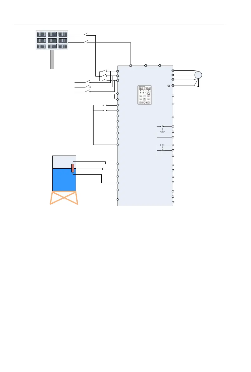
PV panels
Q1
R/L1
S/L2
T/L3
+24V
DI1
DI2
DI3
DI4
DI5
DI6
+10V
AI1
AI2
GND
PE
U/T1
V/T2
W/T3
485+
485-
GND
R1A
R1B
R1C
M
(-) (+) PB
PV200
Y2/HO
PLC
DI7/HI
COM
AI3
AO1
GND
+24V
Y1
AO2
GND
R2A
R2B
R2C
KM1
KM2
+
-
Note:KM1 and KM2
is a pair of
interlocking
contactors
Grid or
generator set
PV Voltage
Given selection
Operation panel
Tank
The water
level sensor
RUN/STOP
Short film
Figure 2-4 Grid or Generator Power Supply Wiring Diagram 2
1. Wirings as Figure 2-3 system wiring drawings according to inverters power, check and confirm
the connections to be correct.
2. Disconnect the switch Q1, and then close Q2, switch to grid or diesel engine power;
disconnect Q2, and then close Q1, switch to PV power supply; Figure 2-4 show inter-locking
connection between connector KM1 and KM2, KM1 close is PV power supply, KM2 close is
grid or generator power supply.
3. When grid or generator power supply, setting H00.01=0, power supplied by grid.
4. For water pump’s frequency, please refer to F01 group code, H00.02~H00.12 function code
does not work.
5. When change to PV power supply, setting F04.1=38 and close the terminal DI2 (or setting
H00.01=1).
Note:
When the bus input terminal does not install the diode protection, PV panel switch Q1 will be
prohibited to close together with grid power input switch Q2, or the panel will be damaged.
 Loading...