PV series Solar Pumping Inverter
- 19 -
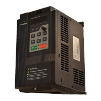
DI1
+24V
DI2
PLC
DI3
COM
DI4
DI5
COM
DI6
Y1
Y2
+10V
R1A R1B
R1C
R2A R2B
R2C
AO1
AI1
GND
AI2
485+
AI3
485-
PE
DI7/HI
AO2
GND
Figure 2-16Control Terminals Diagram
Table 2-2 PV200 Inverter Control Circuit Terminal Functions
Output +10V Power Supply, Maximum
Output Current: 10mA. Generally use for
power supply of external potentiometer,
resistance range of potentiometer: 1~
5kΩ
Output +24V power supply, generally use
for power supply of digital input/output
terminal and external sensor, maximum
output current: 200mA.
External Power
Input Terminal
Factory default in connection with +24V,
when using an external signal to drive
DI1~DI7, PLC need to be connected to
external power, and disconnected with
+24V power terminal.
Input Range: DC 0~10V/0~20mA,
selected by AI1、AI2 toggle switches on
control board. Input Impedance: 250kΩ
for voltage input, 250Ω for current input.
Input voltage range: DC -10~+10V
Input Impedance: 250kΩ
Maximum input frequency: 200Hz
Input Impedance: 2.4kΩ
Voltage Range of level-input:9V~30V