PV series Solar Pumping Inverter
- 18 -
Main
winding
Secondary
winding
U1
U2
Z1
Z2
M
(-) (+) PB
PV200
KM1
L1
L2
U
V
W
220VAC
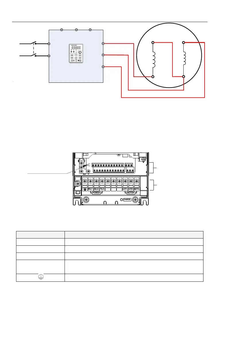
Figure 2-14 Reverse wiring between VFD PV200 (Above 0.75Kw) and motor
After wiring completed, need to set F08.00=2.
2.4 Product Terminal Configuration
2.4.1 Main Circuit Terminals
0.75~200KW main circuit terminals
Control circuit
terminals
Main circuit
terminals
Upload and
download interfaces
PB
(+)
(-)
RFI
Figure 2-15 0.75~200kW Main Circuit Terminal Diagram
Table 2-1 Functions of Inverter Main Circuit Terminals
AC Power Input Terminal, connected to three-phase 380V AC power.
Inverter AC output terminal, connected to three-phase AC motor
Respectively to be positive and negative terminal of internal DC bus
Braking resistor connection terminals, one end connected to (+), the
other end of PB.
Ground terminal, connected to the earth.
2.4.2 Control Circuit Terminals