S90-020 M FRICK
®
QUANTUM™ LX COMPRESSOR CONTROL PANEL
Page 10 MAINTENANCE
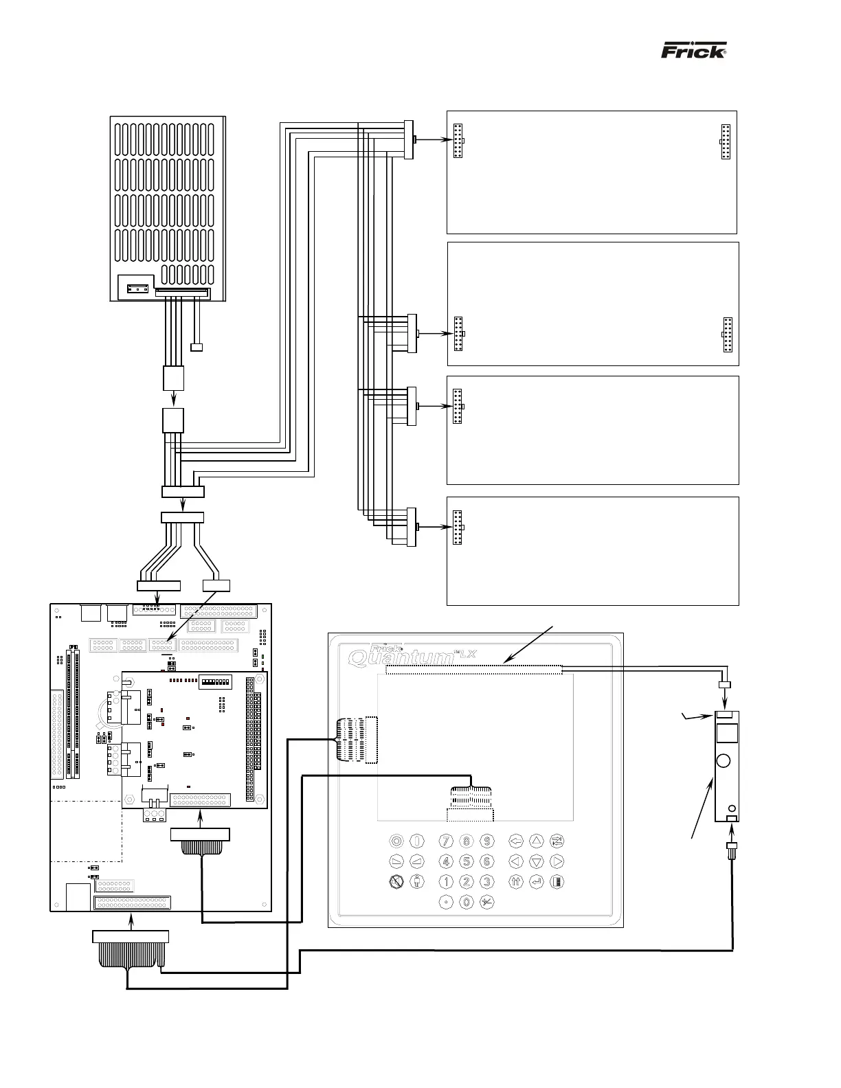
QUANTUM™ LX FLOW DIAGRAM - D.C. VOLTAGE/COMMUNICATIONS HARNESS (SPECIAL)
Quantum™ 4
Backlight Tube (refer to Display Assembly
Component Replacement Guide)
Caution!
High AC voltage at
this connector.
Display (refer to Display
Assembly Component
Replacement Guide)
Keypad Cable
P/N
640B0031H01
Inverter
P/N
333Q0001582
Display/Inverter Cable
P/N 649D4824H01
Flash Card
socket
located under
board
1
2
3
4
3
2
1
Quantum™ 4 Adapter
Harness
P/N 649B0862H01
Digital Board 1
Digital Board 2
Analog Board 2
Analog Board 1
Power
Supply
(Condor
shown
.
Factory
Connector
DC Power -
I/O Communications
Harness
P/N 640B0038H01
This pictorial represents a typical configuration using the Quantum™ 4 in a special
panel, and is not to scale. Specific units may or may not have both Digital and Analog
boards, depending on options. Additionally, the power supply may vary. The pictorial is
meant to show the proper interconnection of the D.C. power - I/O communications
harness, ke
board cable and dis
la
harness and hardware com
onents.
1
2
4