FRICK
®
QUANTUM™ LX COMPRESSOR CONTROL PANEL S90-020 M
MAINTENANCE Page 7
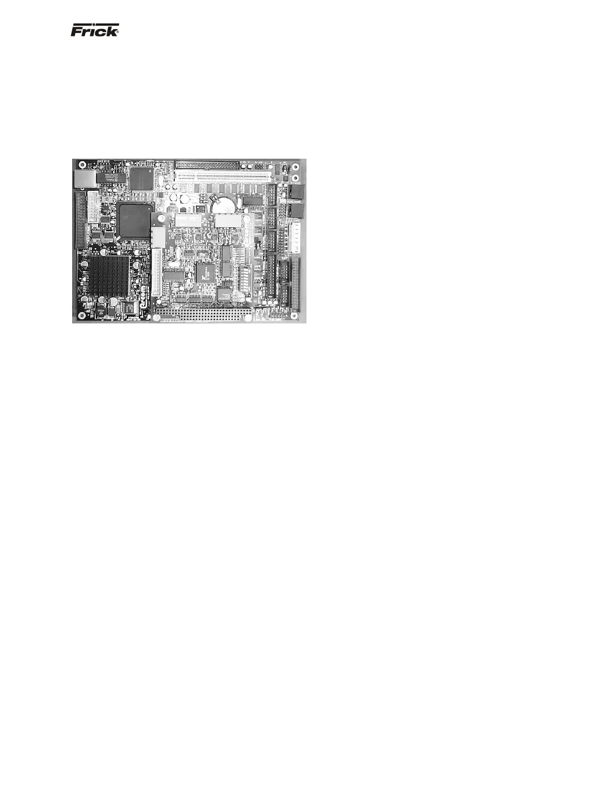
QUANTUM™ CONTROLLER BOARD
INTRODUCTION
Frick
®
Controls has strived to remain on the cutting edge of
microprocessor technology and development. Because of
the ever-increasing speed, memory eatures, and power of
microprocessors, Frick
®
will continue to introduce the latest
advancement in microprocessor control technology.
Quantum™ LX
TROUBLESHOOTING THE QUANTUM™ CONTROL
PANEL
This section contains information on troubleshooting and
making corrections to the boards and control circuits of the
Quantum™. Refer to the drawings at the end of this
manual.
GENERAL INFORMATION
The components within the control panel can be
inadvertently damaged by static electricity or
mishandling. Only qualified technicians should
directly handle these components.
1. DO NOT attempt to make corrections to the
power supply without shutting off the power to the
control panel. Accidental shorts can irreparably
damage the processor boards or the display
screen.
2. DO NOT HANDLE the panel boards when their
cables are disconnected without first attaching a
properly grounded wrist ground strap to prevent
static electrical discharge from your body.
Most problems encountered with the microprocessor and
control circuits will be the result of a wiring fault, a blown
fuse, faulty I/O module or failure of a peripheral control
such as a solenoid coil or a pressure transducer. Faults in
the computer, while possible, are unlikely. If a fault
develops in the computer, the probability is that all
functions will cease and the display screen will go blank.
The control system of the compressor consists of an AC
(high voltage) side, which can be either 120 volts, or 230
volts, and a DC (low voltage) side. The AC side actuates
solenoids, relays, alarms, and other electromechanical
functions. The DC side operates the computer and it's
various sensors.
When working within the panel, the AC high voltage
side, which can be either nominal 120 VAC or nominal
230 VAC, CAN CAUSE INJURY OR DEATH.
To troubleshoot the low-voltage side of the control circuits,
it is necessary to have the following tools:
1. Accurate digital multimeter (capable of reading to
the hundreds of a volt)
2. Small wire stripper
3. Small screwdriver (with insulated shaft)
4. Small snip nose pliers
5. Wrist Grounding strap
6. Static free grounded work surface
Note: Proper panel voltage refers to the AC (high volt-
age) that has been supplied to the panel, which could
be either nominal 120 VAC or nominal 230 VAC
(Reference the Control Panel Power Specifications).
Some problems that are encountered involve
troubleshooting the panels digital inputs and outputs. The
Digital I/O (Input/Output) boards have six Digital I/O (DIO)
board connectors labeled P1 through P6. The input and
output modules are wired into a DIO connector plug.
Position 3 provides power and position 4 is a neutral on
the DIO connectors.
WHAT TO DO BEFORE CALLING THE FACTORY
Many times when a suspected Quantum™ problem is
called in to the factory, not enough information is provided
for the service personnel to assist in solving the problem.
This is because the caller most likely is not aware of the
type of information that would be useful to factory
personnel in helping to identify and correct the problem.
An example of this is the statement that the Quantum™ is
not booting (the main processor board is not starting).
Unfortunately, this description is usually vague and only
means that there is nothing on the display. A blank screen
could be the result of many different problems. Following
is a list of possible reasons for no display:
• No power
• Loose or Faulty Display Cable or Inverter Cable
• Bad Display
• Bad Backlight Inverter
• Bad Backlight Fluorescent Tube
• Wrong Combination of Display, Cable, Inverter,
or Software
• Faulty CPU Board
Before calling the factory for assistance, review the
information on the following pages and try to discover and
resolve your Quantum™ problem. The actual cause of
most problems is usually not with the Quantum™ itself,
but with something external. However, on the rare
occasion that the problem has been identified as being the
Quantum™ controller, use the following section as a
guideline for replacing it.
REPLACING THE QUANTUM™ BOARD
The Flash Card memory load is done prior to the board to
the board shipping. The customer needs to have their
settings manually recorded, or saved to a Flash Card, so