FRICK
®
QUANTUM™ LX COMPRESSOR CONTROL PANEL S90-020 M
MAINTENANCE Page 13
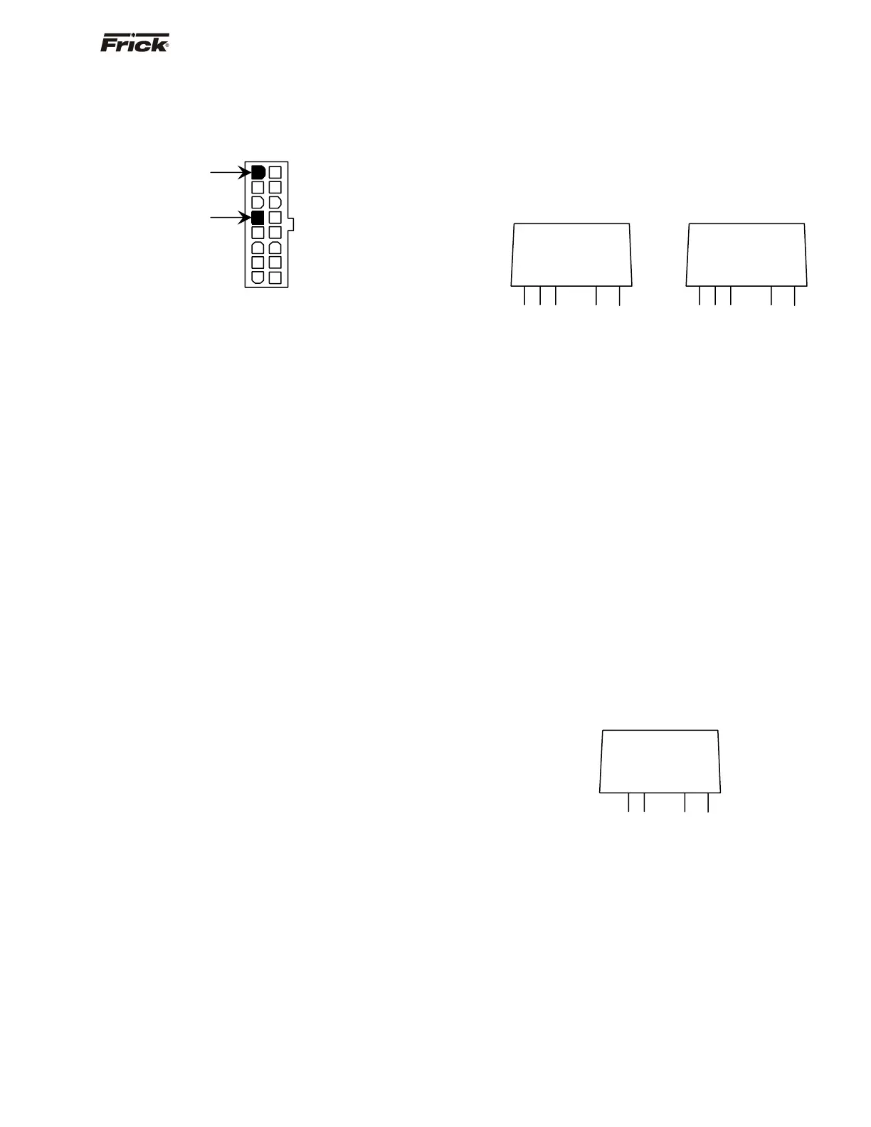
will only be plugged into one of these connectors. Take
the red (positive) probe of the DVM and carefully insert the
end into the "+5V" lead, and the black (negative) probe
end into the "RET" (Return or Common) lead, as shown
below:
Set the DVM to read DC, and set the proper range. The
voltage reading must read a minimum of +4.98 Vdc. The
Power-I/O harness will have an associated voltage drop at
each board connection. As an example, if you are reading
the voltage at the first I/O board in the daisychain, and it
reads 4.98 Vdc, you can be assured that the voltage at the
subsequent connections for the remaining boards will be
lower yet. The voltage will need to be corrected for proper
operation of the system. The cause for a low voltage
reading could be:
• The Quantum™ power supply may need
adjustment (see the section on power supplies).
• The Power-I/O communications harness has a
problem (a new harness may be needed).
• A problem may exist with one of the I/O boards
(Digital or Analog).
• If the power LED is not lighted, check the cable
for proper connectivity. Note: Each board
provides the necessary connections to feed
all signals to the following connectors. If the
auxiliary Analog or Digital Board is not
present then a jumper plug (see
Recommended Spare Parts List) must be
installed to daisychain the signals.
The most common symptom that is be exhibited by a low
+5 Vdc voltage to the Digital Boards is an alarm message
that reads Digital Board Reset Shutdown.
Active LED
The Digital Boards have an Active LED indicator on the
board that blinks when the board’s software is running.
If the Active LED is not blinking, check to ensure that the
EPROM is installed properly. The EPROM is located in
chip slot U8, next to the power connector.
Digital Inputs
A Digital Input is the portion of the hardware that allows
devices such as limit switches, relay contacts, and level
switches, to interface with the Quantum™. The software
program within the Quantum™ LX is constantly looking at
these Input channels, via communications, and based
upon whether a control voltage is present or not, will
provide the necessary control for an associated Output
channel. For instance, if a control voltage is present on the
Oil Level Sensor input, the software will determine that the
Separator has sufficient oil level for the oil heaters to be
energized (if the temperature of the oil is also sensed to
be low. Temperature sensing will be discussed in the
Analog Input section).
There are two possible varieties of Digital Input modules
used on standard compressor control packages. One is for
120 Volt controls, and the other is for 240 volt controls.
Both of these module styles are yellow in color. A side
profile of these modules is shown below:
These Input modules, can be identified as to their
operating voltage by looking at either the side, as shown
above, or from the top. You will notice the module
operating voltage printed on the top, and the voltage range
printed on the side.
Never plug a 120 Volt Input module into a 240 Volt
system, and vice-versa. Never plug an Output module into
a position designated for an Input module.
You will notice that when a module is plugged into the
Digital board, there is a fuse located directly adjacent to
the module. This fuse is of the plugable variety, and must
be plugged into the IN position for an Input module.
Digital Outputs
A Digital Output is the portion of the hardware that the
Quantum™ is to control (energize). These devices include
solenoids, relay coils, and heaters to be energized, based
upon the logic within the Quantum™ LX software program.
There is one variety of Digital Output modules used on
standard compressor control packages. This one module
will handle both 120 Volt controls, and 240 volt controls.
This module is black in color. A side profile of this module
is shown below:
Although this Output module is labeled as 280 VAC on the
top, and on the side, it can be used on both 120 and 240
volt applications.
Never plug an Input module into a position designated for
an Output module.
You will notice that when a module is plugged into the
Digital Board, there is a fuse located directly adjacent to
the module. This fuse is of the plugable variety, and must
be plugged into the OUT position for an Output module.
+5V
RET
5
-
4
+
3
+
COM OUT VDC
5VDC LOGIC
2
1
90-140VAC
AC INPUT
120 VAC Input
5
-
4
+
3
+
COM OUT VDC
5VDC LOGIC
2
1
180-280VAC
AC INPUT
240 VAC Input
4
-
3
+
3-8 VDC
DC CONTROL
2
∼
1
3A 280VAC
AC OUTPUT
120/240 VAC Output