FRICK
®
QUANTUM™ LX COMPRESSOR CONTROL PANEL S90-020 M
MAINTENANCE Page 19
Communications LED's
The Quantum™ controller is in constant communication
with the Analog (and Digital) Board(s). You will notice on
each Analog and Digital board, that there is a pair of LED's
that are labeled as RX and TX. These letters represent
receive (RX) and Transmit (TX). These LED's should be
flashing at a high rate during normal operation. This
indicates that the Quantum™ LX, and the board that you
are looking at, are properly communicating with each
other.
• Refer to the JUMPER AND DIPSWITCH
SETTINGS section later in this section. This
section contains the dipswitch settings for
addressing the Analog I/O Boards. When these
switches are properly set, the Quantum™ LX is
able to serially communicate with each I/O board
and provide control signals and data exchange. If
these switches are not properly set, the result
can be one of the following:
• Lost or failed communications (displayed in
the Communications Status box on the
Home screen)
• The wrong analog input signals being
received
• The wrong analog output signals being sent
from the board.
Connections to the Quantum™
As stated earlier, the Quantum™ standard compressor
control system utilizes up to two Digital, and two Analog
Boards. To connect all of these boards together so that
the Quantum™ can control them, they must be
interconnected with a wiring harness that provides all of
the necessary D.C. voltage requirements, as well as the
communications capabilities. A diagram of this wiring
harness can be found later in this addendum (see the
Power I/O Wiring Harness drawing). This harness has an
18-pin connector at one end that plugs into the
Quantum™. Another connector plugs into the power
supply. The remaining four connectors (16 pin) will plug
into each of the Digital and Analog Boards in the system
(up to four total).
Upon close examination of this harness, you will notice
that each of the connectors for both the Quantum™ and
the four I/O boards, have two rows of connections. The
wires that are inserted into the positions of one row, are
internally daisychained on each I/O board, to continue the
voltages and signals to the adjacent row. Therefore, any
time that a connector is unplugged from the daisychain,
these voltages and signals cannot continue through to the
next board. Whenever a plug is not to be inserted onto a
board, either for servicing, or if not all boards are present
because of the options that are present, then a shunting
plug (refer to the Recommended Spare Parts list) must be
installed onto the open connector.
The four wires that feed from the power supply to the
Quantum™ provide all of the necessary D.C. voltage that
is required (+5 Vdc, -12 Vdc, +12 Vdc, and Return or
Common). The voltages are passed through the connector
on the Quantum™, and two new signals are generated by
the Quantum™ to be passed on through the daisychain to
the I/O boards. These two signals are the RX (receive)
and TX (transmit). These signals are the means by which
the Quantum™ LX communicates to the I/O.
The Analog Board requires the +5 Vdc for logic, the
-12 Vdc for internal voltage reference, and +12 Vdc for
external sensors (plus or +) and the Return (common or -).
The communications signals (RX & TX) are required by all
boards.
Logic Voltage (Power) LEDs
Located on the enhanced Analog Board are two power
LEDs. The first of these is D1 LED (+5Vdc), and will be
illuminated as long as the Control Power switch is ON, and
the proper voltage is present at Analog Board connector
P3. The power supply generates the +5 Vdc voltage, and
passes it on through the Power-I/O harness. This LED
does not indicate however that the proper voltage is
necessarily present at the board, only that the voltage is
enough to energize the voltage sensing circuitry.
If a voltage related problem is suspected with regard to an
Analog Board, the best way to actually determine this is to
read the voltage on a DVM (Digital Volt Meter). This may
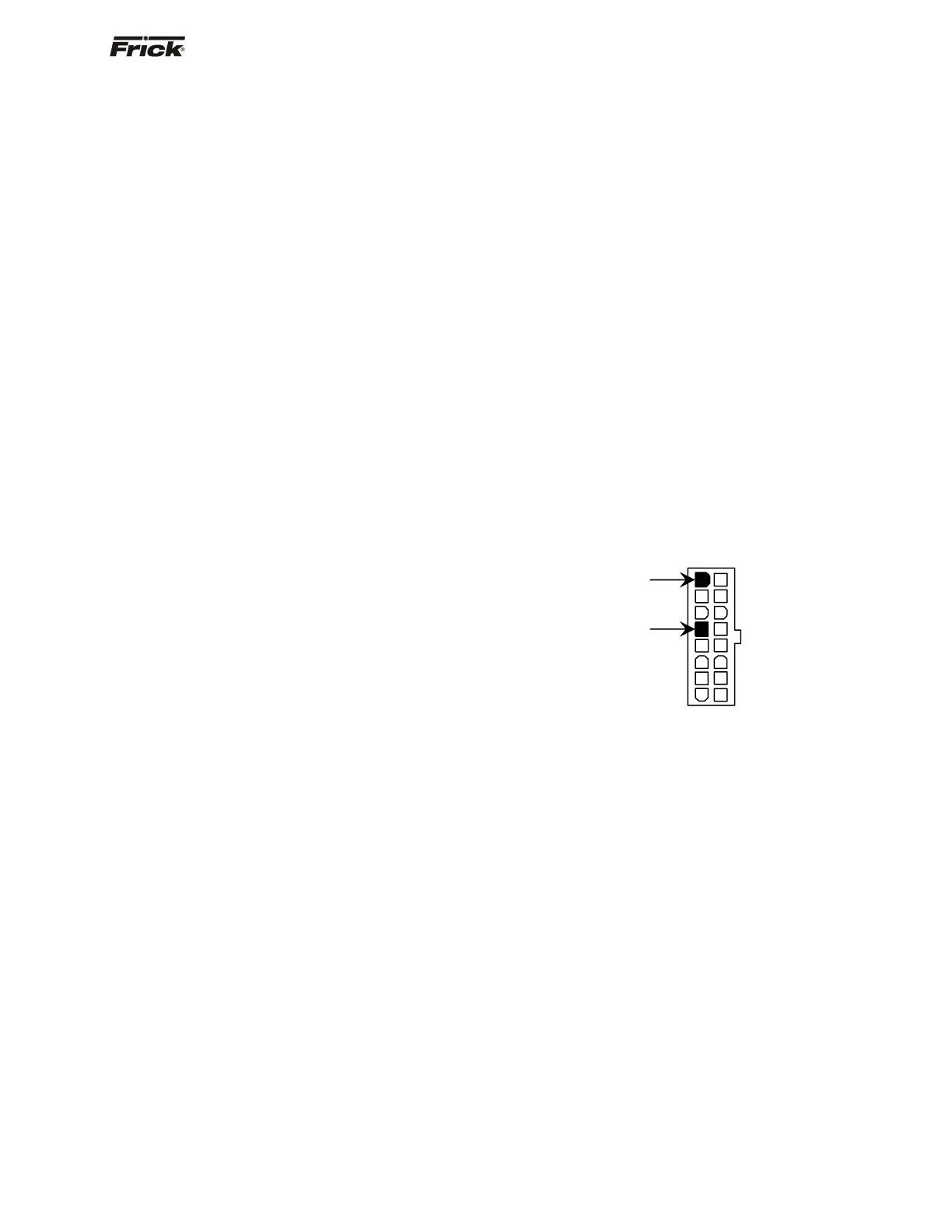
be accomplished by locating the white power /
communications connector on the board. Notice that the
Analog Board has only one of these connectors. The
associated power/communications harness plugs in to it.
Take the red (positive) probe of the DVM and carefully
insert the end into the +5V lead, and the black (negative)
probe end into the RET (Return or Common) lead, as
shown below:
Set the DVM to read DC, and set the proper range. The
voltage reading must read a minimum of +4.98 Vdc. The
Power-I/O harness will have an associated voltage drop at
each board connection. As an example, if you are reading
the voltage at the first I/O board in the daisychain, and it
reads 4.98 Vdc, you can be assured that the voltage at the
subsequent connections for the remaining boards will be
lower yet. The voltage will need to be corrected for proper
operation of the system.
The cause for a low voltage reading could be:
• The Quantum™ power supply may need
adjustment (see the section on power supplies).
• The Power-I/O communications harness has a
problem (a new harness may be needed).
• A problem may exist with one of the I/O boards
(Digital or Analog).
• If the power LED is not lighted, check the cable
for proper connectivity. Note: Each board
provides the necessary connections to feed
all signals to the following connectors. If the
auxiliary Analog or Digital Board is not
present then a jumper plug (Part #
640B0039H01) must be installed to daisychain
the signals.
The second power LED is D5 (+24Vdc). This +24Vdc
voltage is generated on the Analog Board from the +5Vdc
+5V
RET