S90-020 M FRICK
®
QUANTUM™ LX COMPRESSOR CONTROL PANEL
Page 18 MAINTENANCE
ANALOG BOARD
Overview
The Frick Quantum™ LX control panel is capable of
reading external analog devices, such as temperature
probes and pressure sensors. It uses these input signals
for the purpose of monitoring and control. As an example,
if an external temperature sensor began to read a higher
than expected temperature in some area, the controller
would sense this change, and provide the necessary
output control signal to remedy the situation. Unlike a
digital signal, which is typically either an on or off state, an
analog signal can assume a wide variety of states, such
as a temperatures probe reading a wide range of
temperatures.
The method used for receiving (and sending) these
signals, is the analog board. The analog devices are wired
directly to the board, and the on-board software/hardware
converts the electrical signals recieved from these devices
into data, which is then sent on to the Quantum™ LX
control board via communications, and is monitored by the
Operating system.
Analog Board Versions
There have been two different varities of Analog Board
which have been used:
• Original - This board featured sixteen input and
four output channels. The board also required
jumpers to be manually set for each channel, so
that the signal could be properly interpretted by
the hardware. This board has been discontinued
as of June 2003 and replaced by a newer
version, which improves the capabilities and
enhances the features. The description in this
manual will concentrate on the new (enhanced)
analog board design, with occasional mention of
the original design as a reference. If additional
information is required regarding this earlier
version board, please consult S90-010 M Ver.
4.5x and earlier, or contact the factory. A drawing
of this board is shown here:
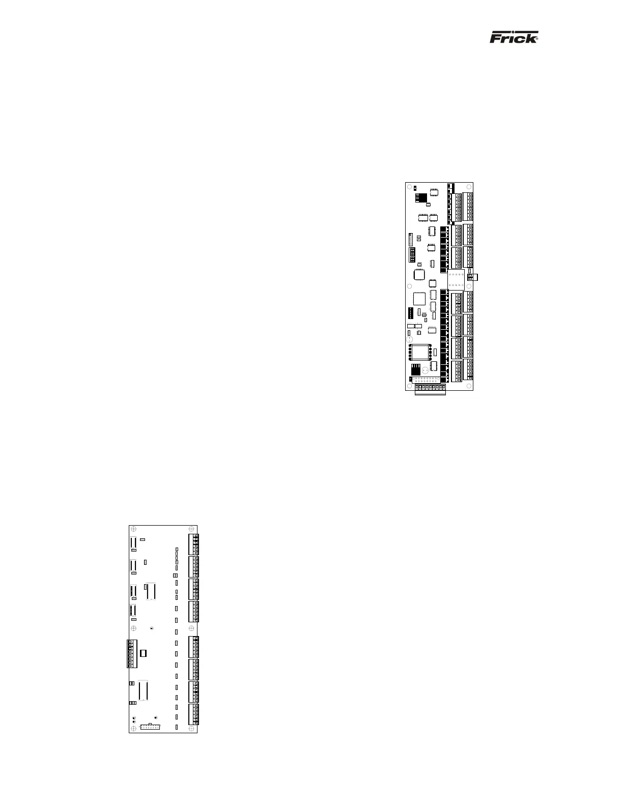
• Enhanced - This board replaces the oiginal
analog board effective June 2003. It features
twenty-four input channels, and eight output
channels. Rather than using physical jumpers to
configure each channel, this is now done through
the software. A more detailed description of the
operation of this board is provided in the sections
that follow. A drawing of this board is shown
here:
Analog Board Description
The Analog Board is actually a small microprocessor
board and is programmed to control analog outputs, or
accept analog inputs, from external electrical devices.
Each enhanced board has the capability of 24
independent input channels. With the Quantum™
Compressor Control, these I/O channels are dedicated
through the software and external wring, as to the function
of each channel. The Quantum™ controller can utilize up
to two separate analog boards (Analog Board #1 and #2),
depending on the selected options. This can consist of any
combination of Original (16 channels) or Enhanced (24
channels) boards (as long as the Quantum™ LX operating
software is version 6.0x or later). For example, board #1
can be of the original design, while board #2 can be of the
enhanced design.
For each of the boards that are installed, they will each
have specific I/O (Input / Output) functions. For the
operating software to distinguish board #1 from #2, each
board must be properly addressed as #1 and #2 using the
dipswitches on each board (see Analog Board Dipswitch
Settings chart for this information). This allows the
operating software to know what channel of which board a
signal is being recieved from.
For example, the first channel of Analog Board #1 is
dedicated to reading Suction Temperature. By having the
dispswitches set correctly, the sowftware will know which
of the two possible boards to look at in order to read the
correct channel one. NOTE: Although the function of this
channel cannot be changed, the type of device wired to it
can be.