S90-020 M FRICK
®
QUANTUM™ LX COMPRESSOR CONTROL PANEL
Page 34 MAINTENANCE
POWER SUPPLY IDENTIFICATION, ADJUSTMENT AND REPLACEMENT
IDENTIFICATION
Frick
®
Controls has used two power supplies in the
Quantum™ family. A Power One supply was originally
used, primarily with the Quantum™ 1 & 2. With the
introduction of the Quantum™ 3, the power supply vendor
was changed to Condor. This same Condor supply is also
now used with the Quantum™ 4 (LX).
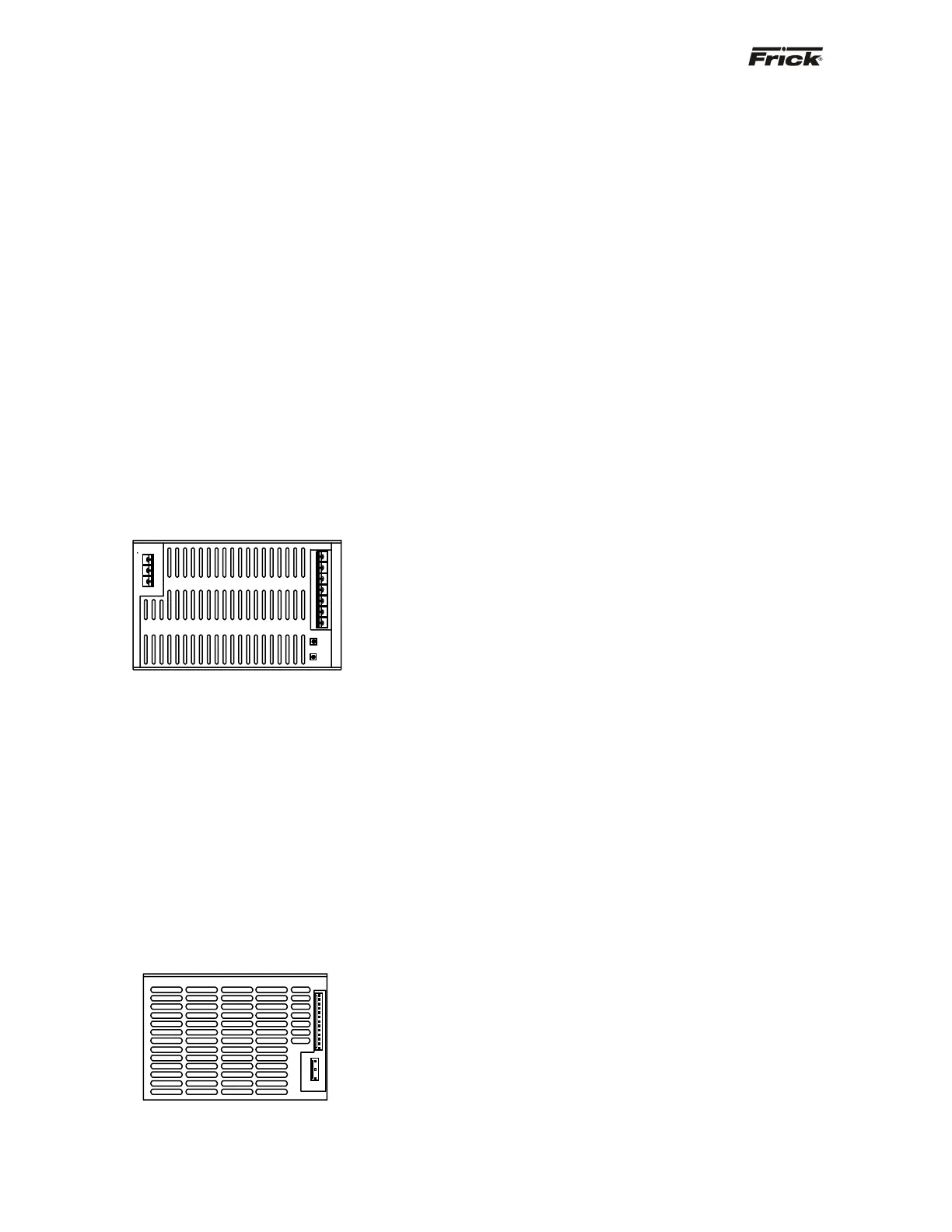
Power One - This power supply may be identified by
the location of the AC and DC power connections,
they will be found at opposite ends of the supply.
These connections are of the screw terminal type.
Additionally, the lower left hand corner of the front grill
will have two access holes. The left most of these
holes allows for access to the adjustment
potentiometer for the +5 Vdc output voltage, and the
rightmost of these holes allows for the potentiometer
adjustment of the +12 Vdc output voltage. If the -12
Vdc is out of acceptable range, the power supply will
need to be changed. Extreme care must be used
when adjusting either of these potentiometers.
Adjustment should only be performed by qualified
personnel, using an insulated screwdriver.
Power One Power Supply
Condor - This power supply may be identified by the
location of the AC and DC power connections, they
will be found at the same end of the supply. These
connections are of a push-on multiple contact
connector type. Additionally, there is the capability of
adjusting the +5 Vdc voltage. Refer to the following
page for the location of this potentiometer adjustment.
Unlike the Power One supply, there is no +12 Vdc
adjustment on the Condor. If the +12 Vdc, or -12 Vdc
is out of acceptable range, the power supply will need
to be changed. Extreme care must be used when
adjusting the +5 Vdc potentiometer. Adjustment
should only be performed by qualified personnel,
using an insulated screwdriver.
Condor Power Supply
ADJUSTMENT
All circuit boards within the Quantum™ control panel
require accurately adjusted DC voltages in order to
function properly. These voltages consist of +5 Vdc, -12
Vdc, +12 Vdc and +24 Vdc. Periodic measurement and
adjustment of the DC power system is highly
recommended for optimum system operation. Over time, it
is possible for temperature, humidity, vibration and
component age, to degregate the accuracy of these
voltages. When any of the DC voltages begin to stray from
their optimum range (especially +5 Vdc), mysterious
problems can begin to arise.
All four DC voltages originate from the power supply
(either Power One or Condor). They are then
daisychained to the Quantum™ controller, and then on to
all connected Digital and Analog boards. Refer to the Flow
Diagrams for the Quantum™ 3 and 4.
Even with a perfectly adjusted supply, it is possible for a
potential drop in voltage at each connection point within
the daisychain. This drop normally is in the mill-volt range,
but under some conditions, the drop can be much greater
(as high as tenths of a volt). By the time the voltage
reaches the last board in the daisychain, and all of these
potential voltages drops are considered, the combined
drop can be such that serious problems can be apparent.
Some examples of serious problems could be:
• Loss of, or intermittent communications failures.
• A shurdown message stating Digital Board x
Reset (where “x” is replaced by the number of the
Digital Board that failed)
• An shutdown message stating Digital Board x
Comm. Fail - Shutdown (where “x” is replaced by
the number of the Digital Board that failed)
• An shutdown message stating Analog Board x
Comm. Fail - Shutdown (where “x” is replaced by
the number of the Analog Board that failed)
• Numerous sensor fault shutdown messages.
• Quantum™ LX reboots for no apparent reason.
• Improper readings of analog pressures and
temperatures.
• LED's on the Quantum™ are lit, but nothing
appears on the display.
It must be pointed out that neither the -12 Vdc nor the +24
Vdc are adjustable. Additionally, the +12 Vdc may only be
adjusted on the Power One supply (+12 Vdc cannot be
adjusted on the Condor). +5 Ddc can be adjusted on both
supplies.
In order to properly measure the DC power, it must be
checked at the Quantum™ controller, and verified for
acceptable total voltage drop at the end of the daisychain
(last I/O board). For the +5 Vdc (on either power supply), if
the voltage at the Quantum™ is in the range of +5.04 to
+5.08 (+5.06 is ideal), and the voltage being read at the
last I/O board is greater than +4.98 V, it can be assumed
that the +5 V power is correctly adjusted. For the +12 Vdc
(on either power supply), if the range at the last I/O board
is between +11.8 and +12.2 Vdc (+12.00 is ideal), it can
be assumed that the +12 V power is correct. The range for